Signal transmission method, system and device for system joint networking
A time slot and time technology, which is applied in the field of signal transmission and can solve problems such as implementation schemes for reducing mutual interference of signals
- Summary
- Abstract
- Description
- Claims
- Application Information
AI Technical Summary
Problems solved by technology
Method used
Image
Examples
Embodiment 1
[0083] This embodiment is a basic configuration scheme, that is, the power ramp-up time of the base station transmitter is not considered, and the details are as follows:
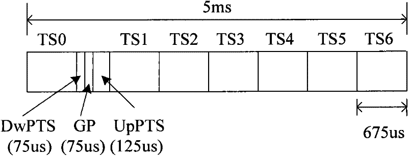
[0084] Ta: Indicates the time occupied by uplink time slots (UpPTs+uplink service time slots) in a radio frame of the TD-SCDMA system;
[0085] Tb: Indicates the time occupied by uplink time slots (UpPTs+uplink business time slots) in a wireless frame of the TD-LTE system;
[0086] According to the relationship between Ta and Tb, if the frame structures of the two systems can coexist, that is, there is no signal interference, there are the following two situations, which are analyzed as follows:
[0087] Case 1: If Figure 4A As shown, Tb>Ta, in this case, if the frame structures of the two systems can coexist, the following conditions need to be met:
[0088] TaCDMA ;
[0089] Case 2: If Figure 4B As shown, Tb
Embodiment 2
[0099] This embodiment is a supplementary configuration scheme, that is, considering the power ramp-up time of the base station transmitter, the details are as follows:
[0100] In actual equipment, it takes a certain amount of equipment switching time for the base station to switch from uplink reception to downlink transmission. In the TD-SCDMA system, there are always 16 chips of idle time after each time slot that can be used for equipment switching, but This switching time is not reserved in the frame structure of TD-LTE. This makes it necessary for the terminal of the TD-LTE system to consider the switching time of UL→DL at the base station side when transmitting, and to perform early transmission. Specific as Figure 5A Shown:
[0101] in, Figure 5A The timing advance shown in includes not only the UL→DL switching time to ensure the base station side, but also the terminal signal transmission time due to the distance. The current standard preliminarily determines th...
Embodiment 3
[0122] Embodiment 3: The scheme of closing some time slots
[0123] In this embodiment, the TD-SCDMA system 4:3 (uplink time slot: downlink time slot) is used to illustrate the solution.
[0124] Step 1: According to the description in the second embodiment, determine the available TD-LTE time slot configuration, and find that there is no available time slot configuration, that is, for the 4:3 time slot configuration structure in the TD-SCDMA system, there is no The available TD-LTE subframe structure can coexist with it;
[0125] Step 2: For the time slot configuration structure of 4:3 in the TD-SCDMA system, determine the TD-LTE frame structure configuration 2:1:2 with the least intersecting time slot with the time slot configuration structure; Figure 6A shown;
[0126] Step 3: The UpPTs in the 4:3 time slot configuration structure in the TD-SCDMA system are transferred (shifting), it is moved to the end of the time slot 1 (TS1) of TD-SCDMA and aligned with the end, such ...
PUM
 Abstract
Description
Claims
Application Information
 - R&D
- Intellectual Property
- Life Sciences
- Materials
- Tech Scout
- Unparalleled Data Quality
- Higher Quality Content
- 60% Fewer Hallucinations
Browse by: Latest US Patents, China's latest patents, Technical Efficacy Thesaurus, Application Domain, Technology Topic, Popular Technical Reports.
© 2025 PatSnap. All rights reserved.Legal|Privacy policy|Modern Slavery Act Transparency Statement|Sitemap|About US| Contact US: help@patsnap.com


