Subsea Control System Diagnostics

A technology of hydraulic control system and subsea control module, which is applied in fluid pressure actuation system testing, wellbore/well components, instruments, etc., and can solve the problems of expensive and time-consuming subsea equipment failure intervention or maintenance

Inactive Publication Date: 2011-11-30
CHEVROU USA INC
View PDF7 Cites 10 Cited by
  • Summary
  • Abstract
  • Description
  • Claims
  • Application Information

AI Technical Summary

Problems solved by technology

[0001] Intervention or overhaul of subsea equipment failures can be expensive and time consuming

Method used


Image

  • Subsea Control System Diagnostics
  • Subsea Control System Diagnostics
  • Subsea Control System Diagnostics

Examples


Embodiment Construction

[0018] Introduction to the control system

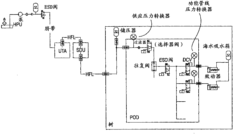
[0019] figure 1 is a schematic diagram of a general hydraulic control system. At sea, hydraulic fluid is pumped from a hydraulic power unit (HPU) into an umbilical that terminates in an umbilical termination assembly (UTA). For projects with long guy lines, the control fluid should be modeled as a compressible flow in the umbilical. Through the Subsea Distribution Unit (SDU), a series of tree valves are opened through DCVs controlled by the SCM. Subsea accumulators provide a localized source of pressure to help open valves faster, as well as cushioning to absorb shocks and irregularities in the flow. Leakage of the precharge gas may cause the pressure accumulator to lose its function, and thus, may affect the performance of the entire hydraulic control system. Subsea filters help keep hydraulic fluid clean. Dirty fluids can cause damage to the flow passages, as well as failure of, for example, solenoid valves. The actuator used...


PUM


Abstract

Accurate, dependable methods for analyzing operational parameters of subsea control systems and diagnosis / prediction of failures are provided, in particular, methods for detection of leaking and / or clogging in hydraulic control system using recorded pressure signals and evaluating response communication strength (signal amplitude) of field equipment from, for example, subsea control systems. Prediction of failure(s) allows an opportunity to prepare for intervention to minimize the impact of failure before failure occurs, for example, by ordering equipment, tools and / or scheduling an intervention vessel. Similarly, diagnosing a failure drastically shortens the intervention time.

Description

Background technique [0001] Intervention or overhaul of subsea equipment failures can be very expensive and time-consuming. If problems can be diagnosed and / or predicted before a system fails, significant operational savings can be gained from the project by planning interventions before the system fails. [0002] Hydraulic control systems of subsea equipment are critical components whose integrity greatly affects the functionality of subsea production systems. All means should be used to prevent or repair the failure of the hydraulic control system as soon as possible to ensure the normal operation of the subsea production system. Some common failure modes associated with hydraulic control systems include, for example, supply / function line or Directional Control Valve (DCV) leaks, subsea filter plugging, accumulator pre-charge gas escaping, and Actuator spring force and seal friction vary. [0003] Traditional methods of predicting subsea hydraulic failures rely on operato...

Claims


Application Information

Patent Timeline
Patent Type & Authority Applications(China)
IPC IPC(8): F15B19/00G01M3/28G01M99/00
CPCF15B19/005G01M3/26E21B33/0355F15B19/00G01M99/00
Inventor B·T·坦茹安海岭A·卡拉姆昌丹尼
Owner CHEVROU USA INC
Why Eureka
Try Eureka