chimeric structure

A chiming structure and meshing technology, which is applied to transmission devices, components with teeth, elastic couplings, etc., to achieve the effect of reducing abnormal noise

Active Publication Date: 2011-11-30
TOYOTA JIDOSHA KK
View PDF4 Cites 5 Cited by
  • Summary
  • Abstract
  • Description
  • Claims
  • Application Information

AI Technical Summary

Problems solved by technology

[0006] Therefore, in the above-mentioned conventional planetary gear mechanism, when the torque transmitted from the engine to the planeta

Method used


Image

  • chimeric structure
  • chimeric structure
  • chimeric structure

Examples


Embodiment Construction

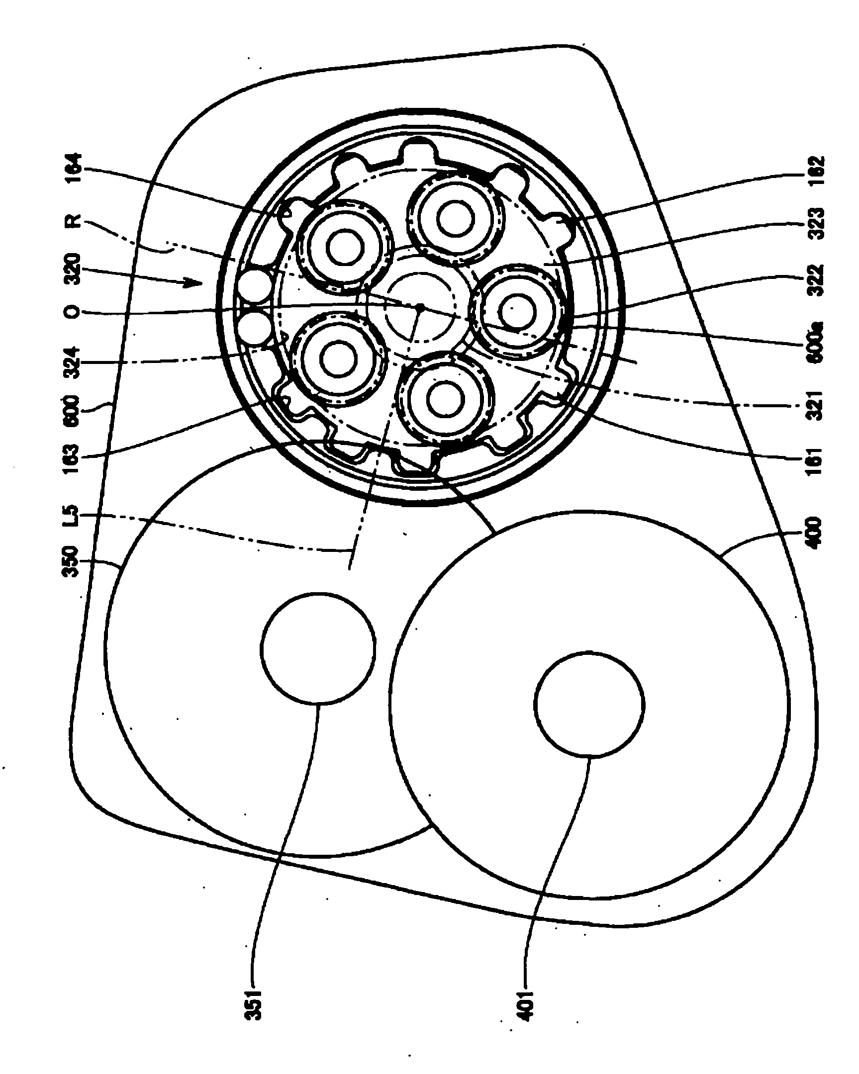
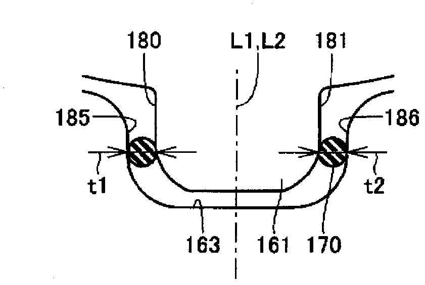
[0030] use Figure 1 to Figure 12 The fitting structure of the planetary gear mechanism and the gearbox according to the present invention will be described. In addition, in the embodiments described below, when referring to the number of objects, the amount, and the like, the scope of the present invention is not necessarily limited to the number, amount, and the like unless otherwise specified. In addition, in the following embodiments, each component is not an essential component to the present invention, unless otherwise specified.

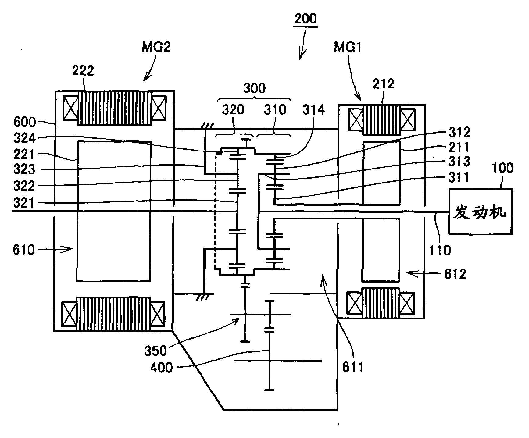
[0031] figure 1 It is a schematic diagram showing the structure of a hybrid vehicle to which the interfitting structure according to the embodiment of the present invention is applied.

[0032] refer to figure 1 , the hybrid vehicle is equipped with a driving device 200 for rotating the driving wheels, and the driving device 200 includes: an engine 100, a motor generator (Motor Generator) MG1, MG2, a power distribution mechanism (power tran...


PUM


Abstract

A fitting structure has a power transmission member (323) which includes first and second tooth sections (161, 162) arranged at intervals at the outer peripheral edge of the power transmission member and to which power is transmitted, and the fitting structure also has a fitting member (600) which is placed so as to surround the power transmission member (323), has formed therein first recesses (163) for receiving the first tooth sections (161) and second recesses (164) for receiving the second tooth sections (162), and fits to the power transmission member (323). The distance between the outer surface of a first tooth section (161) and the inner surface of a first recess (163) is set greater than the distance between the outer surface of a second tooth section (162) and the inner surface of a second recess (164), and an elastically deformable cushioning member is provided between the outer surface of the first tooth section (161) and the inner surface of the first recess (163).

Description

technical field [0001] The present invention relates to a fitting structure, and particularly relates to a fitting structure including a power transmission member that transmits power and a fitting member that is fitted to the power transmission member. Background technique [0002] Conventionally, a planetary gear mechanism embedded in a gear case of a vehicle has been widely known. For example, the planetary gear mechanism described in Japanese Unexamined Patent Application Publication No. 2006-183824 includes: a sun gear; a pinion gear positioned outside the sun gear and meshing with the sun gear; and a ring gear positioned outside the pinion gear. outboard and meshes with the pinion. Furthermore, each pinion is rotatably supported by a planet carrier, and the planet carrier is fitted into the gear case. [0003] A plurality of protrusions are formed on the outer peripheral portion of the planet carrier, and a plurality of recesses for receiving the protrusions are form...

Claims


Application Information

Patent Timeline
IPC IPC(8): F16H57/02F16H57/08F16H57/00
CPCF16D3/12F16H57/082F16D3/68F16H37/10F16H57/0006F16H2057/02034Y10T74/19679
Inventor 竹中达史中田明梶原彰人
Owner TOYOTA JIDOSHA KK
Why Eureka
Try Eureka