Ship Propulsion Plant Using Hydraulic Thrust Bearing

A technology of thrust bearings and propulsion devices, which is applied in bearings, shafts and bearings, mechanical gear transmissions, etc., can solve the problems of increasing additional space and additional expenses, reducing the concealment of ships in combat, and achieving good shock and noise reduction effects. The effect of saving equipment space and cost

Inactive Publication Date: 2011-12-07
ZHEJIANG UNIV
View PDF6 Cites 22 Cited by
  • Summary
  • Abstract
  • Description
  • Claims
  • Application Information

AI Technical Summary

Problems solved by technology

The motor 1 and the gearbox 3 are installed on the flexible support I 13 and the flexible support II 12 respectively, the motor 1 and the gearbox 3 are connected through the gear coupling 2, and the gearbox 3 and the thrust bearing output shaft 24 are connected through the flexible coupling 23 Compensate for relative radial displacement, which greatly increases additional space and additional expenses
In addition, the thrust bearing box 8 is connected to the hull through the rigid support 11, and the structural vibration noise caused by the axial force is inevitably transmitted through the thrust pad 6, the upper support block 7, the lower support block 22, the thrust bearing box 8 and The rigid support base 11 is introduced into the hull of the ship, causing the excitation of the hull structure and reducing the concealment of the ship's combat

Method used


Image

  • Ship Propulsion Plant Using Hydraulic Thrust Bearing
  • Ship Propulsion Plant Using Hydraulic Thrust Bearing
  • Ship Propulsion Plant Using Hydraulic Thrust Bearing

Examples


Embodiment Construction

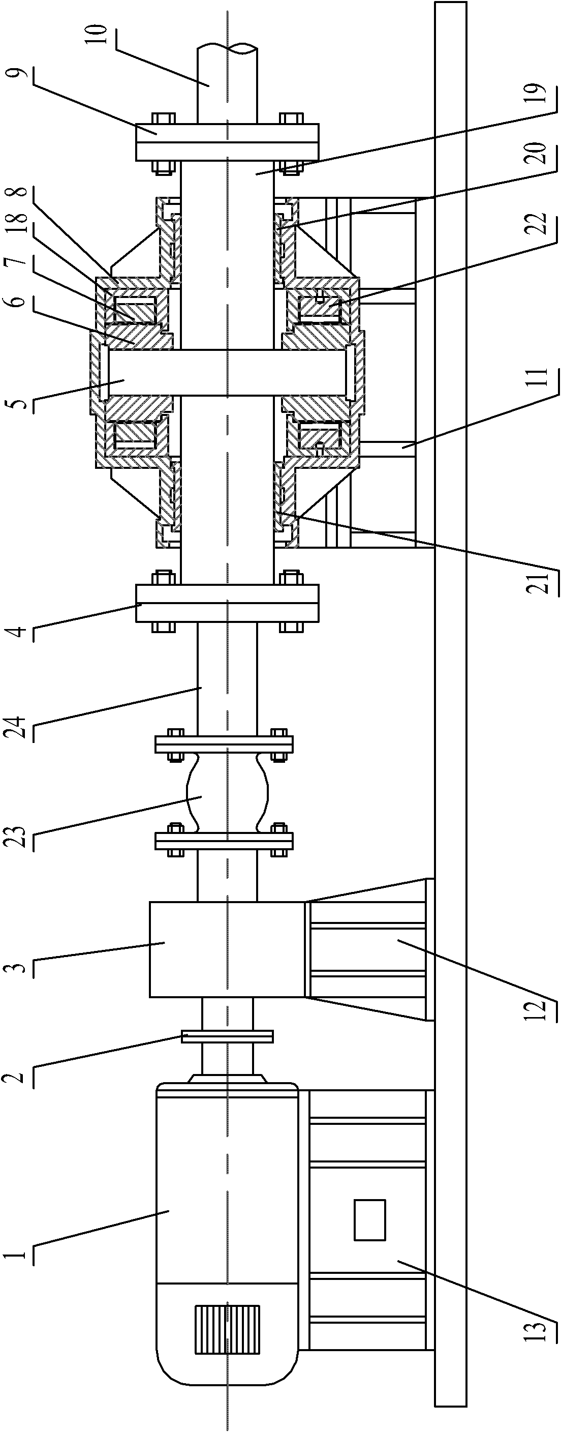
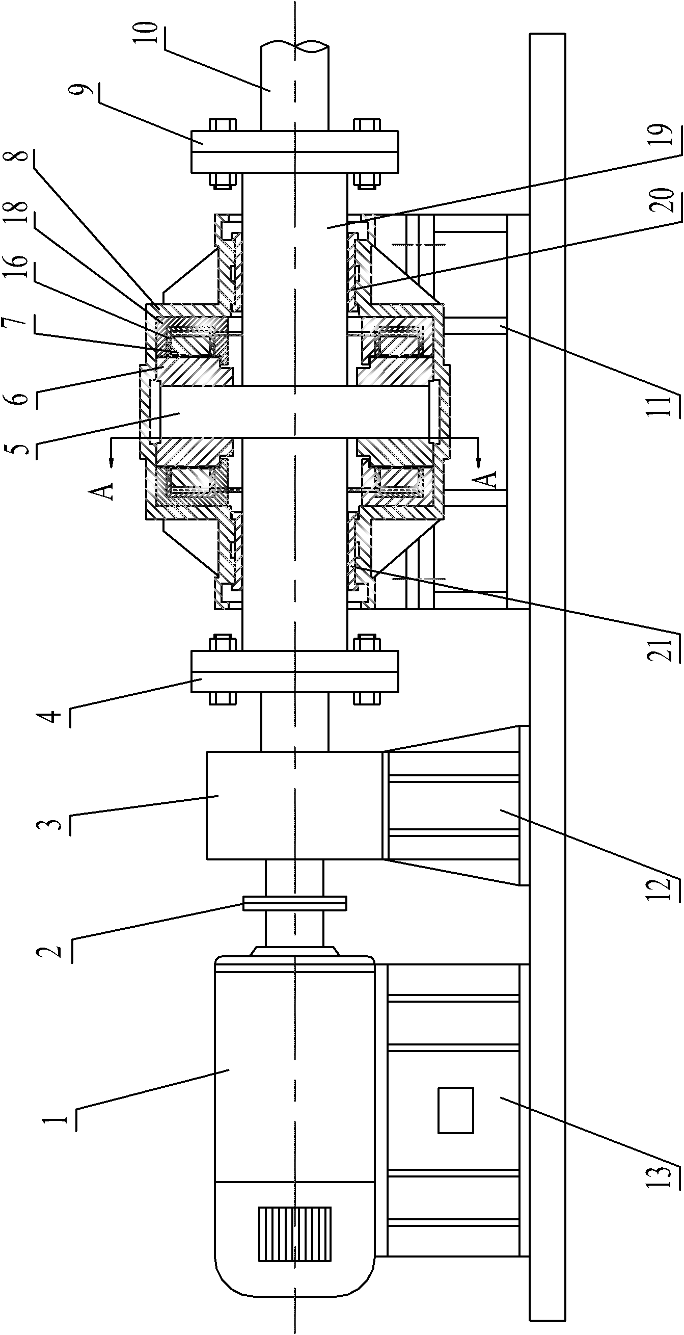
[0026] Figure 2 ~ Figure 4 Combined with a ship propulsion device using hydraulic thrust bearings, including motor 1, gear coupling 2, gearbox 3, flange I 4, hydraulic thrust bearing device, flange II 9 and propulsion shaft 10 . The motor 1 is installed on the flexible support I 13 (same as the prior art), and the gearbox 3 is installed on the flexible support II 12 (same as the prior art), thereby effectively reducing the structural vibration noise of the motor 1 and the gearbox 3 . The motor 1 and the gearbox 3 are connected through a gear coupling 2 .

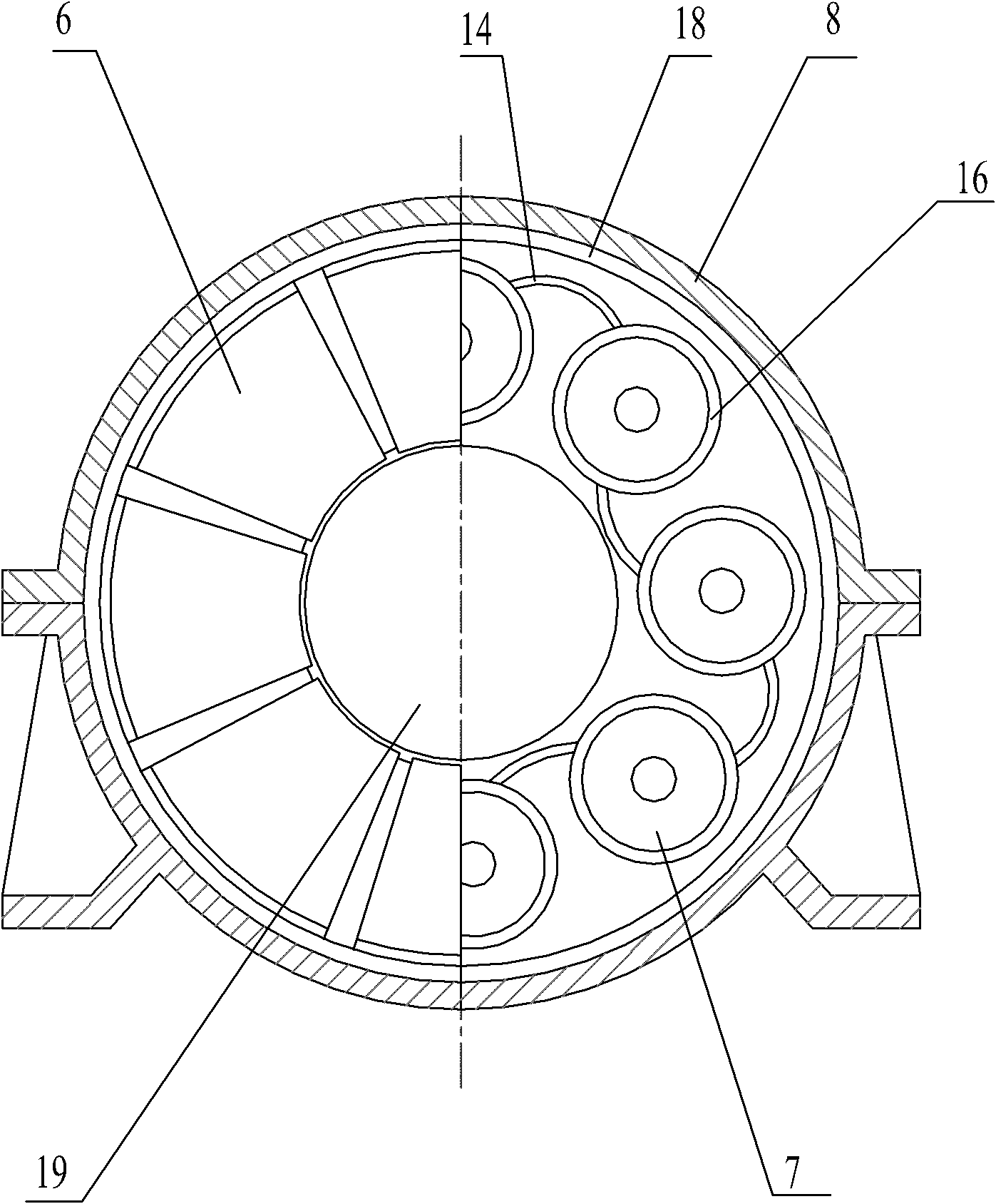
[0027] The hydraulic thrust bearing device includes a thrust bearing housing 8 which is fixedly connected to a rigid support 11 . The left end face and the right end face of the thrust bearing housing 8 are provided with through holes respectively; after the thrust shaft 19 runs through the thrust bearing housing 8 transversely, the left end of the thrust shaft 19 is connected to the output shaft of the gear box 3 through...


PUM


Abstract

The invention discloses a ship propulsion device adopting a hydraulic thrust bearing, comprising a motor (1) and a hydraulic thrust bearing device, etc., the hydraulic thrust bearing device includes a thrust bearing box (8), and a thrust bearing box (8) is equipped with There is a thrust shaft (19), and the two ends of the thrust shaft (19) are respectively connected with the output shaft of the gearbox (3) and the propulsion shaft (10); a thrust disc (5) is also arranged in the thrust bearing box (8) , the thrust disc (5) is perpendicular to the thrust shaft (19) and is fixedly connected with the thrust shaft (19); a set of hydraulic cylinder assemblies are respectively provided on the left and right sides of the thrust disc (5), and each set of hydraulic cylinder assemblies and thrust A set of thrust pads is arranged between the discs (5); the lower surface of the thrust pads (6) is provided with a spherical convex portion (61), and the spherical convex portion (61) forms a point bearing contact with the piston support block (7). Using the ship propulsion device can effectively reduce the structural vibration and noise radiation level of the ship shell.

Description

technical field [0001] The invention relates to a ship propulsion device adopting a hydraulic thrust bearing, which is especially suitable for military ship equipment such as warships and submarines with high requirements on vibration and noise levels. Background technique [0002] Thrust bearing is one of the key equipment of ship propulsion shafting. Its main function is to transmit the power of the power plant to the propeller, and transmit the thrust or pull generated by the propeller to the hull to make the ship move forward or backward. While the thrust bearing is transmitting force, the pulsating thrust received by the propeller is transmitted to the shell structure through the propulsion shafting, thrust bearing, bearing support structure and bearing base. During this process, the thrust bearing system acts as a vibration transmission carrier. Therefore, the performance of the thrust bearing not only directly affects the reliability of the ship's power system, but al...

Claims


Application Information

Patent Timeline
Patent Type & Authority Applications(China)
IPC IPC(8): B63H23/02F16C32/06
Inventor 黄滨王乐勤吴大转郭嘉
Owner ZHEJIANG UNIV
Why Eureka
Try Eureka