An engine plastic intake manifold

A technology of intake manifold and engine, which is applied in the direction of engine components, machine/engine, charging system, etc., and can solve the problem of easy formation of overflow in the inner air passage

Inactive Publication Date: 2011-12-07
CHONGQING CHANGAN AUTOMOBILE CO LTD
View PDF8 Cites 7 Cited by
  • Summary
  • Abstract
  • Description
  • Claims
  • Application Information

AI Technical Summary

Problems solved by technology

[0004] The invention proposes a plastic intake manifold for an engine, which mainly solves the problem that the internal air p

Method used


Image

  • An engine plastic intake manifold
  • An engine plastic intake manifold
  • An engine plastic intake manifold

Examples


Embodiment Construction

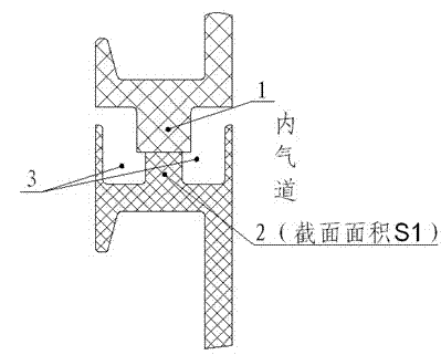
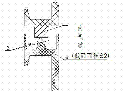
[0011] see figure 2 , the plastic intake manifold is divided into upper and lower parts and welded. In the part that needs to be welded, the structure of the friction rib 1 of the upper piece remains unchanged, and the ordinary welding structure, that is, the welding rib of rectangular section is designed Welding bar 4, the cross-sectional area of ​​the welded bar 4 of trapezoidal cross-section is the same as the cross-sectional area of ​​the welded bar 2 of the original rectangular section (i.e. figure 1 S1 in is equal to figure 2 S2 in ).

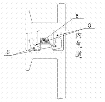
[0012] Such as image 3 As shown, the hot melt 5 generated by the vibration and friction of the trapezoidal cross-section welding rib 4 will be stored in the overflow tank 3 during welding, and 6 in the figure is the welding volume. Because the volume of the overflow tank 3 on the inner air passage side of this structure is larger than the traditional overflow tank volume, that is, the overflow tank on the air passage side in the int...


PUM


Abstract

The invention relates to an engine plastic intake manifold, which is divided into upper and lower pieces, which are formed by vibration friction welding, one of which has friction ribs at the welding position, and the other has welding ribs at the welding position, and overflows on both sides of the welding ribs Material trough; characterized in that: the cross-section of the welding rib is trapezoidal structure. Due to the use of trapezoidal cross-section welding ribs in this structure, the volume of the overflow tank on the side of the inner air passage is larger than that of the traditional structure, and can accommodate more hot melt, which can avoid the leakage of the air passage in the intake manifold. Form flash to ensure the surface finish of the air passage in the intake manifold.

Description

technical field [0001] The invention relates to an engine intake manifold, in particular to an engine plastic intake manifold. Background technique [0002] The intake manifold is an important part of the engine. Its function is to evenly distribute the air or oil-air mixture to each cylinder of the engine to participate in combustion. At present, the performance of plastic synthetic materials has been continuously improved, which can meet the performance requirements of engine intake manifolds, so many automobile engines have adopted plastic intake manifolds. [0003] In terms of technology, plastic intake manifolds are mostly formed by vibration friction welding of pieces. Due to vibration and friction welding, part of the material needs to be melted away, and a certain amount of hot melt is likely to remain in the air passage after welding to form flash. See figure 1 , the welding part of the ordinary plastic intake manifold, the upper piece has friction ribs 1, and the...

Claims


Application Information

Patent Timeline
IPC IPC(8): F02M35/104
Inventor 罗昆王奋陈洪文刘波
Owner CHONGQING CHANGAN AUTOMOBILE CO LTD
Why Eureka
Try Eureka