
Intake system with airflow rotation and noise absorber for turbine applications

A technology of air intake system and turbocharger, which is applied in the field of air intake system, can solve the problems that the intake system is easily restricted by airflow, and achieve the effects of less heat, lower noise and increased efficiency

Inactive Publication Date: 2011-12-07
GM GLOBAL TECH OPERATIONS LLC
View PDF8 Cites 4 Cited by
  • Summary
  • Abstract
  • Description
  • Claims
  • Application Information

AI Technical Summary

Problems solved by technology

With these integrated components, the intake system tends to be more susceptible to airflow restrictions

Method used


Image

  • Intake system with airflow rotation and noise absorber for turbine applications
  • Intake system with airflow rotation and noise absorber for turbine applications
  • Intake system with airflow rotation and noise absorber for turbine applications

Examples


Embodiment Construction

[0023] Now see attached picture, Figure 1 to Figure 10 An example of an improved intake system for a turbocharger is shown that minimizes pressure loss, improves the performance of the turbo, and minimizes escape of turbocharger noise.

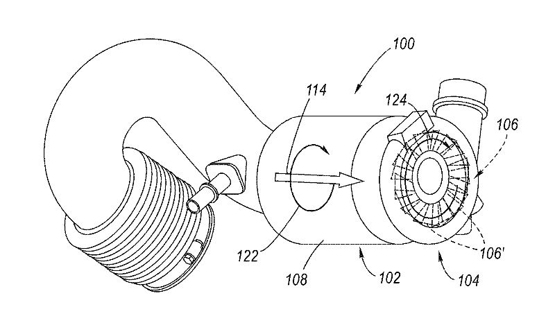
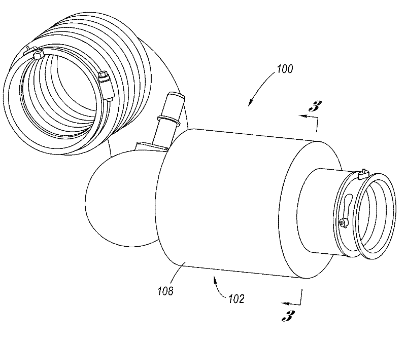
[0024] Figure 1 to Figure 3 An example of an improved air intake system 100 is described, showing an exemplary air intake housing 102 thereof, which may have other configurations (see, e.g., below Figure 10 description of). The intake housing 102 is connected to a turbocharger 104 . Inside the turbocharger 104 is a turbine 106 with blades 106' that rotate in a predetermined direction of rotation 124 in order to draw air from the intake housing 102 arranged upstream and deliver the air, now under pressure to the downstream engine intake manifold (not shown).

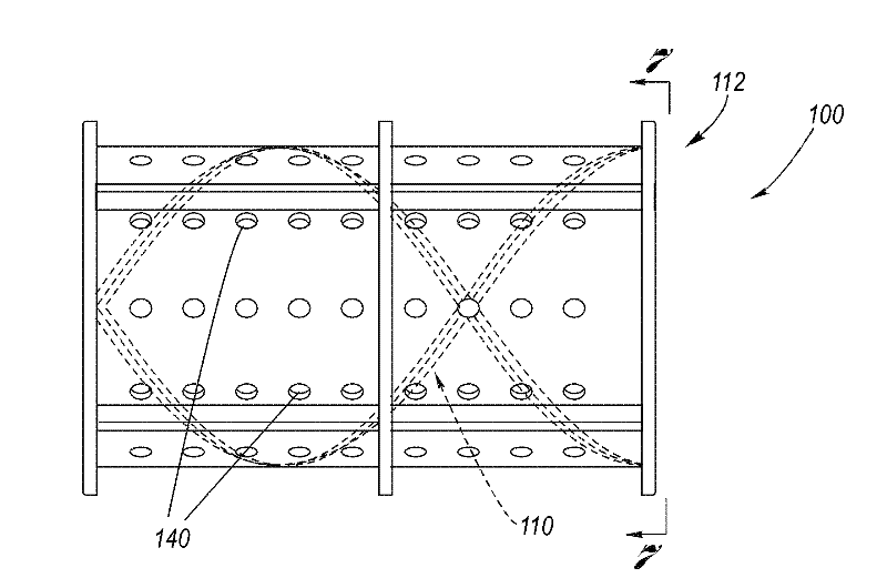
[0025] The intake housing 102 includes a cylindrical main flow duct 108 . Disposed inside the main flow duct 108 is a helical blade 110 , and preferably disposed between the helic...


PUM


Abstract

An air induction system consisting of a cylindrical main flow tube, a helical vane disposed within the main flow tube, and, preferably, a noise absorbing perforated tube disposed within the main flow tube in concentric relation to the helical vane. The twist direction of the helical vane provides air flow rotation in the same direction of rotation as the turbine wheel. The helical vane causes noise reflection and enhancement of noise attenuation by the perorated tube and its adjoining one or more acoustic cavities.

Description

technical field [0001] The present invention relates to an air intake system for a turbocharger, and more particularly to an air intake system that generates an airflow rotation upstream of the turbine of the turbocharger in the same direction as it rotates, and further attenuates the turbine Supercharger noise. Background of the invention [0002] A turbocharger for an internal combustion engine utilizes a rotating turbine that draws air from the upstream intake housing and delivers the air, now under pressure, into the engine's intake manifold downstream. The problem is, turbochargers require power to operate, which includes not only the power needed to spin the turbine, but also the power needed to overcome pressure losses in the intake housing. There is also the problem that the turbocharger generates noise during its operation, which can escape undesirably at the air intake of the intake housing. [0003] When designing an air intake system for a turbocharger, conside...

Claims


Application Information

Patent Timeline
Patent Type & Authority Applications(China)
IPC IPC(8): F02M35/12
CPCF02M35/10157F02M35/1227F02M35/1211F02B37/00F02M35/12F02M35/1216Y02T10/144Y02T10/12
Inventor L.李
Owner GM GLOBAL TECH OPERATIONS LLC
Learn More