A kind of impeller structure and cross-flow fan

A cross-flow fan and impeller technology, which is applied in the direction of mechanical equipment, machines/engines, liquid fuel engines, etc., can solve the problems of cross-flow fans such as low efficiency, complicated flow conditions, uneven pressure, etc., and achieve small pressure difference and high pressure Uniform, uniform air effect

Inactive Publication Date: 2011-12-07
GUANGDONG CHIGO AIR CONDITIONING
View PDF8 Cites 6 Cited by
  • Summary
  • Abstract
  • Description
  • Claims
  • Application Information

AI Technical Summary

Problems solved by technology

The impeller structure in the existing cross-flow fan is shown in figure 1 , figure 2 As shown, it includes a fixed frame 1, and a row of blade groups with multiple blades 2 with the same structure, shape and size are arranged in the fixed frame. Since this type of impeller structure is only provided with one row of blade groups, when the airflow passes through the impeller, , is affected by the two forces of the blades, and flows out from the air outlet. Since the flow of the airflow in the impeller is very complicated, the airflow velocity field is not stable. Therefore, the impeller structure with a single row of impellers in the prior art is in the impeller memory. With a large number of vortexes and a large eccentric vortex, the existence of the eccentric vortex makes the pressure uneven, the pressure difference is large, the air volume is small, and the backflow is generated, resulting in low efficiency of the cross-flow fan

Method used


Image

  • A kind of impeller structure and cross-flow fan
  • A kind of impeller structure and cross-flow fan
  • A kind of impeller structure and cross-flow fan

Examples


Embodiment Construction

[0026] In order to enable those skilled in the art to better understand the technical solutions of the present invention, the present invention will be further described in detail below in conjunction with the accompanying drawings and specific embodiments.

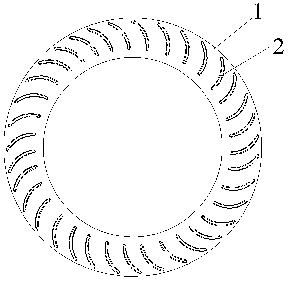
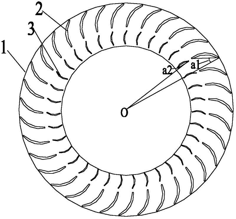
[0027] see image 3 , Figure 4 , The impeller structure in this embodiment includes a fixed frame 1, a first row of blade groups arranged near the outside of the fixed frame, and a second row of blade groups arranged near the inside of the fixed frame.

[0028] Wherein, a plurality of blades 2 are arranged in the first row of blade groups, a plurality of blades 3 are arranged in the second row of blade groups, and a plurality of blades 2 in the first row of blade groups are connected with a plurality of blades in the second row of blade groups. 3 are set in one-to-one correspondence, of course, in other embodiments, they may not be set in one-to-one correspondence. The blades 2 and 3 are arranged at a certain distance....


PUM


Abstract

The invention discloses an impeller structure, which includes a fixed frame, in which at least two rows of blade groups are arranged, each row of blade groups includes a plurality of blades, and each row of blade groups is arranged around the axis of the fixed frame. The impeller structure of the present invention is provided with at least two rows of blade groups, so that the air flow is subjected to the force of the blades four times at least four times. Among the at least two rows of blade groups, the blades in the second row of blade groups play an auxiliary role and can play a role. The role of breaking the vortex and guiding the airflow, thereby reducing the eccentric vortex in the cross-flow wind wheel, thereby reducing the air volume of the secondary return flow of the cross-flow fan, increasing the outlet air volume, improving the flow field characteristics, and making the air output more uniform , At the same time, this at least two rows of blades can also break up the large vortex, thereby reducing noise. Wherein, the second row of blade sets plays a role in guiding the airflow, which can change the original flow direction of the airflow, guide the airflow to flow to the other side of the impeller and then flow out of the impeller. The invention also discloses a cross-flow fan.

Description

technical field [0001] The invention relates to the field of fan ventilation, in particular to an impeller structure with double rows of blades and a cross-flow fan provided with the impeller structure. Background technique [0002] The cross-flow fan is an important part of the air conditioner. A common cross-flow fan generally consists of three parts: the impeller, the air duct and the motor. The impeller structure in the existing cross-flow fan is shown in figure 1 , figure 2 As shown, it includes a fixed frame 1, in which a row of blade groups with multiple blades 2 with the same structure, shape and size is arranged. Since only one row of blade groups is provided in this impeller structure, when the airflow passes through the impeller, , is affected by the two forces of the blades, and flows out from the air outlet. Since the flow of the airflow in the impeller is very complicated, the airflow velocity field is not stable. Therefore, the impeller structure with a si...

Claims


Application Information

Patent Timeline
Patent Type & Authority Applications(China)
IPC IPC(8): F04D29/26
Inventor 郑祖义万忠民金听祥陈水荣许文明
Owner GUANGDONG CHIGO AIR CONDITIONING
Why Eureka
Try Eureka