Parallel Flow Heat Exchangers and Room Air Conditioners
A technology for parallel flow heat exchangers and air conditioners, applied in evaporator/condenser, refrigeration and liquefaction, lighting and heating equipment, etc., can solve the problem of uneven temperature distribution in parallel flow heat exchangers, Reduced thermal efficiency, uneven flow of refrigerant, etc., to avoid uneven distribution of refrigerant, high heat exchange capacity and air conditioning energy efficiency, simple and reasonable structure
- Summary
- Abstract
- Description
- Claims
- Application Information
AI Technical Summary
Problems solved by technology
Method used
Image

Examples
no. 1 example
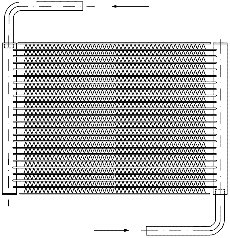
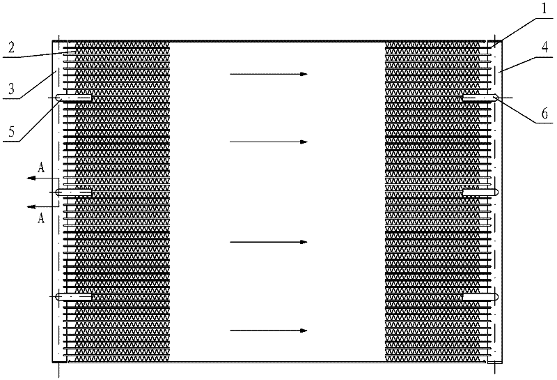
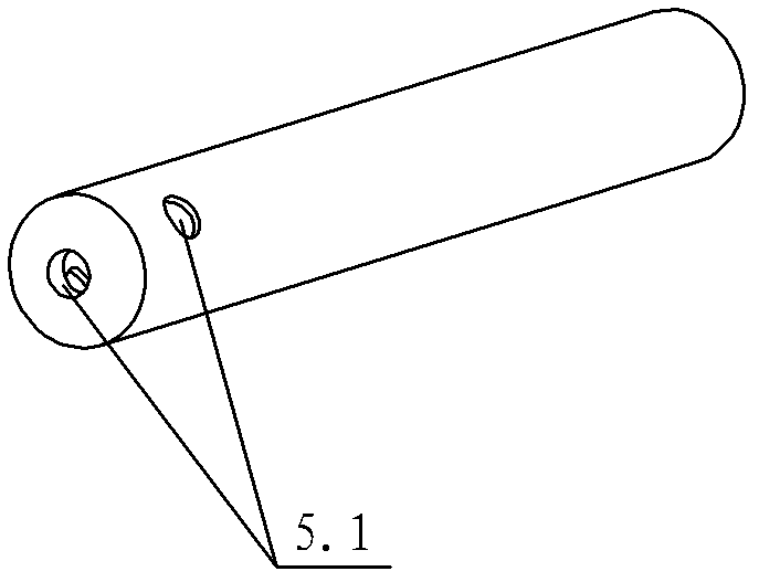
[0027] see Figure 2-Figure 4 , the parallel flow heat exchanger includes a flat tube 1 arranged between the input header 3 and the output header 4, the flat tube 1 is provided with fins 2, and one end of the input refrigerant tube 5 is connected to the input header 3 are connected, one end 6 of the output refrigerant pipe is connected to the output header 4, and more than one first positioning hole is arranged on the side wall of the input header 3, and one end of the input refrigerant pipe 5 is inserted into the first positioning hole One end of the input refrigerant pipe 5 is closed, and one end of the input refrigerant pipe 5 is provided with more than one first small hole 5.1 communicating with the inside of the input header 3; and / or, on the side wall of the output header 4 More than one second positioning hole is provided, one end of the output refrigerant pipe 6 is inserted into the second positioning hole, one end of the output refrigerant pipe 6 is closed, and one en...
no. 2 example
[0034] see Figure 5 , in this embodiment, in order to make the distribution more uniform and the flow resistance smaller, more than one spacer 7 may be provided in the input header 3 and / or the output header 4 .
[0035] The input header 3 and / or the output header 4 are divided into N compartments through partitions 7 . The N partitions are not connected to each other. An input refrigerant pipe is placed in the middle of every two compartments. Each input refrigerant pipe and output refrigerant pipe independently enters and exits refrigerant, and each channel is relatively independent in the input header 3 and / or output header 4 without affecting each other.
[0036] The number of septal regions can be more than two, and the length of each septal region is 20mm-500mm.
[0037] See the first embodiment for the rest of the undescribed parts, and will not repeat them here.
no. 3 example
[0039] see Figure 6 , In this embodiment, the other end of the refrigerant input pipe 5 is connected to the flute-shaped pipe 8; and / or, the other end of the refrigerant output pipe 6 is connected to the flute-shaped pipe 8.
[0040] The input refrigerant pipe and the output refrigerant pipe can be connected through a flute-shaped pipe 8. When the refrigerant passes through the flute-shaped pipe 8, the refrigerant can be transported to each input refrigerant pipe and output refrigerant pipe, and then enter the input header and output respectively. Collector, and then into the flat tube.
[0041] Taking the parallel flow heat exchanger as an indoor evaporator as an example, the input header 3 and the output header 4 are placed horizontally. After being throttled, the refrigerant becomes gas-liquid coexistence state, passes through the flute-shaped pipe 8, and then enters the input refrigerant pipe. At this time, the arrangement direction of the input refrigerant pipe 5 is per...
PUM
 Abstract
Description
Claims
Application Information
 - R&D
- Intellectual Property
- Life Sciences
- Materials
- Tech Scout
- Unparalleled Data Quality
- Higher Quality Content
- 60% Fewer Hallucinations
Browse by: Latest US Patents, China's latest patents, Technical Efficacy Thesaurus, Application Domain, Technology Topic, Popular Technical Reports.
© 2025 PatSnap. All rights reserved.Legal|Privacy policy|Modern Slavery Act Transparency Statement|Sitemap|About US| Contact US: help@patsnap.com