A high-precision geotechnical simple shear instrument and its application method

A high-precision, shear box technology, which is applied in the direction of applying stable shear force to test the strength of materials, can solve the problems of poor reflection, thick stacked rings, and large diameter of displacement sensors, etc., to achieve low cost, Easy-to-implement, simple-structure effects

Inactive Publication Date: 2011-12-07
HOHAI UNIV
View PDF4 Cites 25 Cited by
  • Summary
  • Abstract
  • Description
  • Claims
  • Application Information

AI Technical Summary

Problems solved by technology

[0003] Before the present invention, Chinese patent (patent number: ZL200320114794.1) disclosed a large direct shear instrument for testing the shear strength of coarse-grained soil, Chinese patent (Patent No.: ZL02131066.1) discloses a cyclic loading shear instrument for testing the mechanical properties of the contact surface between soil and structural parts, etc., which are used to analyze the shear properties of soil, etc. This type of instrument has a reasonable structure, small error, and can reflect the , the shear strength of the contact surface between the soil and the structure, and its shortcomings are: 1) The direct shear instrument stipulates that the contact surface of the upper and lower boxes is the failure surface, which does not conform to the actual engineering; 2) Although it can be measured The change law of shear strain at the contact surface, but the overall shear deformation law of the sample cannot be obtained; 3) It cannot be guaranteed that the shear stress is applied in the horizontal direction; 4) The thickness of the contact surface cannot be measured intuitively
[0004] In addition, the Chinese patent (Patent No.: ZL...

Method used


Image

  • A high-precision geotechnical simple shear instrument and its application method
  • A high-precision geotechnical simple shear instrument and its application method
  • A high-precision geotechnical simple shear instrument and its application method

Examples


Embodiment Construction

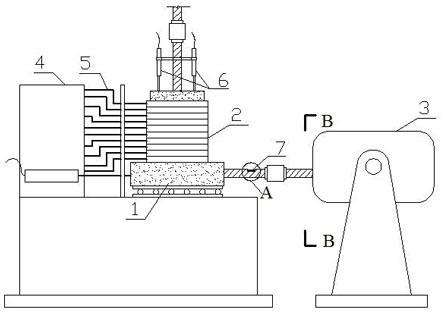
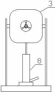
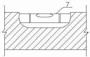
[0032] like Figure 1~5 As shown, a high-precision geotechnical single-shear instrument, its structure is based on the existing single-shear instrument lower shear box (1), upper shear stack ring group (2), and horizontal electromagnetic exciter (3) Add horizontal displacement sensor box (4), displacement sensor connecting rod (5), vertical displacement sensor (6), level pipe (7), jack (8), and place the upper shear stack ring group (2) On the lower shear box (1), grooves are provided on the outer wall of each shear ring inside it, and a plurality of displacement sensors are arranged in the horizontal displacement sensor box (4), wherein the input end of the lowermost displacement sensor is connected to the lower shear The cutting box (1) is connected to measure the shear displacement of the lower shear box (1) during the test, and the input ends of the other sensors correspond to the upper shear stack ring group (2) through the displacement sensor connecting rod (5). The gro...


PUM


Abstract

The invention discloses a high-precision geotechnical single-shear instrument and a use method thereof. Grooves are arranged on the outer wall of each shear ring in the upper shear stack ring group, and a plurality of horizontal displacement sensors and a lower horizontal displacement sensor box are arranged in the horizontal displacement sensor box. The shearing box and the upper shearing ring group are connected; two vertical displacement sensors are placed on the loading top cover; the horizontal electromagnetic exciter is fixed on the base through a jack; the shearing box is connected to the horizontal electromagnetic exciter The level pipe is arranged on the dowel rod horizontally of the device. When in use, the shear force is guaranteed to be applied in the horizontal direction through jack adjustment and level pipe monitoring; the shear displacement generated by each shear ring in the lower shear box and the upper shear stack ring group is collected through the horizontal displacement sensor box; A vertical displacement sensor collects the normal displacement of the sample in the upper shear stack ring group under the action of cyclic shear force. The invention has a simple structure, is easy to implement, and can measure the deformation characteristics of the contact surface between the soil and the structure with high precision.

Description

technical field [0001] The invention belongs to the technical field of civil and water conservancy engineering, and in particular relates to a high-precision geotechnical single-shear instrument and a use method thereof. Background technique [0002] There are many soil-structure contact surfaces in earth-rock dams and roadbeds, and the study of the mechanical properties of the soil-structure contact surfaces is of great significance to the stability of the project. At present, scholars at home and abroad have conducted a lot of research on the mechanical properties of the interface between soil and structures. The instruments used in the research mainly include direct shear instrument, simple shear instrument, dynamic triaxial instrument and torsional shear instrument. Since the simple shear instrument has the function of keeping the contact area unchanged during the shearing process, the state of the soil is closer to K 0 The state and shear failure surface can occur on b...

Claims


Application Information

Patent Timeline
IPC IPC(8): G01N3/24
Inventor 刘平刘汉龙丁选明杨贵
Owner HOHAI UNIV
Why Eureka
Try Eureka