
removable mold

A detachable mold technology, applied in the field of stamping molds, can solve the problems of scrapping, inability to disassemble, long processing process, etc., and achieve the effects of cost reduction, simple structure, and convenient assembly and disassembly

Inactive Publication Date: 2011-12-14
HONG FU JIN PRECISION IND (SHENZHEN) CO LTD +1
View PDF0 Cites 7 Cited by
  • Summary
  • Abstract
  • Description
  • Claims
  • Application Information

AI Technical Summary

Problems solved by technology

This kind of traditional mold has an integral structure, which cannot be disassembled during use, and cannot be shared with other molds. When the punch pin (also known as punch) of the mold is worn out and reaches its service life, the entire mold needs to be scrapped, and the cost of use high
In addition, this integral mold structure is complex and the processing process is long

Method used


Image

  • removable mold
  • removable mold
  • removable mold

Examples


Embodiment Construction

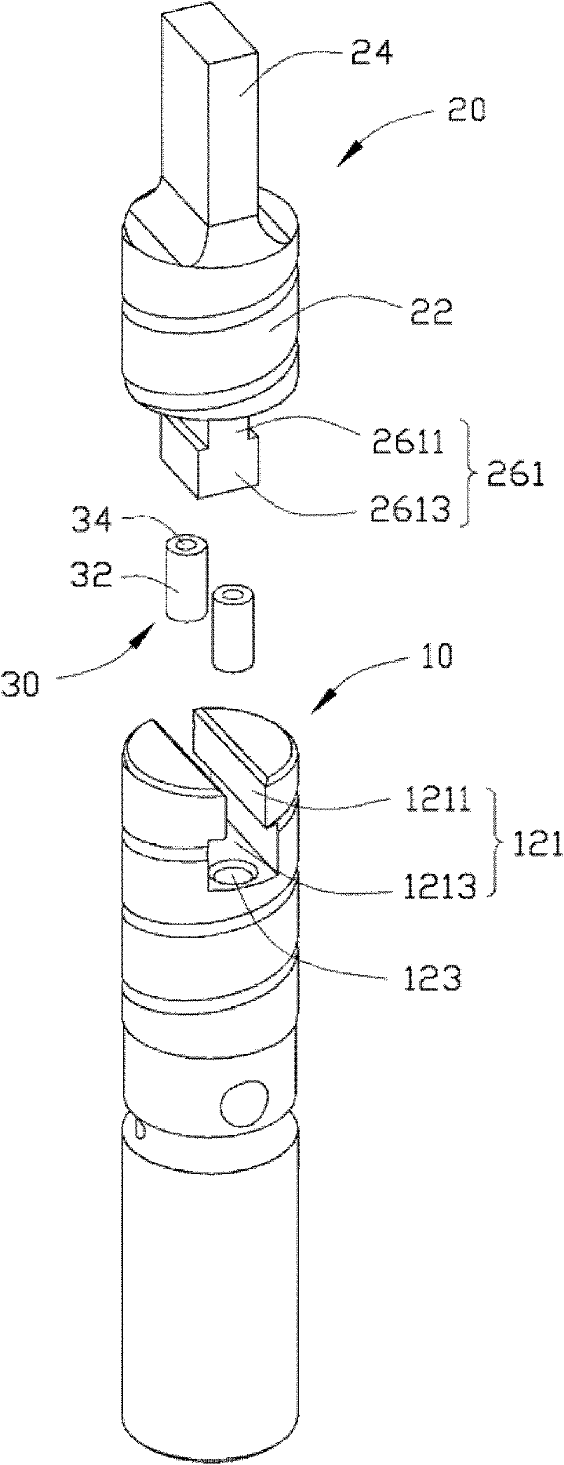
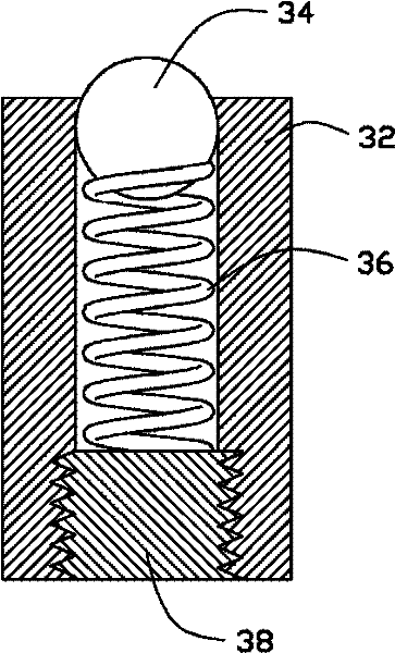
[0028] see figure 2 , The preferred embodiment of the present invention, the detachable mold includes a mold base 10 , a punch 20 and a pair of stoppers 30 .

[0029] The mold base 10 is cylindrical and has a mounting groove 121 on its top. The mounting groove 121 includes a narrower stopper 1211 opened on the top of the mold base 10 and a The wider mounting part 1213 below. The mold base 10 also defines a pair of cylindrical mounting holes 123 downwards at the bottom of the mounting groove 121 for mounting the limiting member 30 .

[0030] The punch 20 includes a cylindrical post 22 , a head 24 protruding upward from the top of the post 22 , and a mounting block 261 protruding downward from the bottom of the post 22 . The mounting block 261 includes a narrow neck 2611 and a wide protrusion 2613 . The width of the neck portion 2611 of the mounting block 261 is equivalent to the width of the limiting portion 1211 of the mounting groove 121 of the mold base 10 . The width o...


PUM


Abstract

A detachable mold, comprising a mold base and a punch detachably mounted on the mold base, the detachable mold also includes a pair of stoppers, each stopper includes an elastic A movable resisting part, the punch pin is limited between the resisting parts of the pair of limiting parts. The detachable mold of the present invention is composed of a plurality of detachable components, has a simple structure and is convenient to assemble and disassemble.

Description

technical field [0001] The invention relates to a stamping die, in particular to a detachable stamping die. Background technique [0002] Stamping die is a special process equipment for processing materials (metal or non-metal) into parts (or semi-finished products) in cold stamping processing, called cold stamping die (commonly known as cold stamping die). The quality, production efficiency and production cost of stamping parts are directly related to the design and manufacture of molds. [0003] Such as figure 1 A traditional stamping die is shown, often used in the sheet metal processing industry. This kind of traditional mold has an integral structure, which cannot be disassembled during use, and cannot be shared with other molds. When the punch pin (also known as punch) of the mold is worn out and reaches its service life, the entire mold needs to be scrapped, and the use cost high. In addition, this integral mold structure is complicated and the processing process ...

Claims


Application Information

Patent Timeline
Patent Type & Authority Applications(China)
IPC IPC(8): B21D37/06B21D37/10B21D37/12B30B15/02
CPCB21D28/34B30B15/065Y10T83/9476
Inventor 蔡随景
Owner HONG FU JIN PRECISION IND (SHENZHEN) CO LTD
Learn More