
A Drilling Method of CNC Milling Machine with Tilting Spindle

A technology of CNC milling machine and processing method, applied in the field of mechanical processing, can solve the problem of lack of drilling processing method of CNC milling machine with tiltable spindle, etc.

Inactive Publication Date: 2011-12-14
NORTHWESTERN POLYTECHNICAL UNIV
View PDF0 Cites 6 Cited by
  • Summary
  • Abstract
  • Description
  • Claims
  • Application Information

AI Technical Summary

Problems solved by technology

[0006] In order to solve the problem of the lack of a drilling method for a CNC milling machine with a tiltable spindle in the prior art, the present invention proposes a drilling method for a CNC milling machine with a tiltable spindle

Method used


Image

  • A Drilling Method of CNC Milling Machine with Tilting Spindle
  • A Drilling Method of CNC Milling Machine with Tilting Spindle

Examples


Embodiment Construction

[0018] Describe the present invention below in conjunction with specific embodiment:

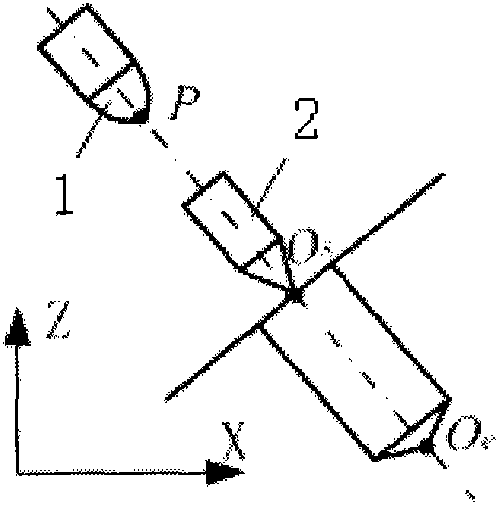
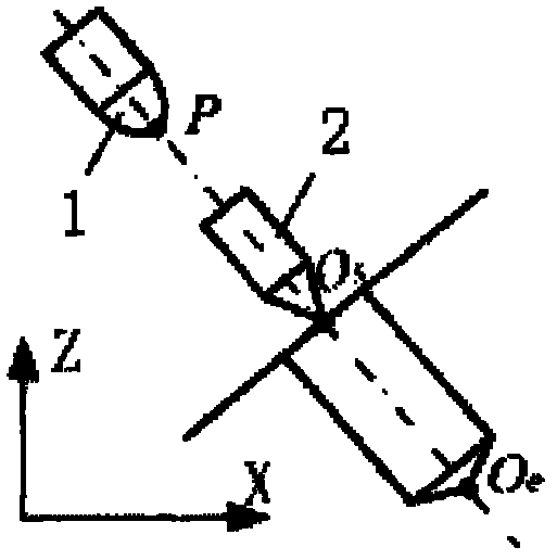
[0019] This embodiment is for drilling the aero-engine casing. Because the blades of the blisk are fixed in the casing, which causes occlusion, ordinary CNC machine tools cannot be processed, and the processing cost is limited, so the five-coordinate machining center cannot be used. CNC milling machine with tiltable spindle for drilling.

[0020] Step 1: Clamp the casing on the machine tool; tilt the machine tool spindle around the Y direction of the machine tool coordinate system, and use a sine gauge to verify the tilt angle, so that the machine tool spindle is perpendicular to the surface of the casing to be drilled; after determining the tilt angle of the machine tool spindle , clamp a standard tool on the machine tool spindle, move the tool so that the central axis of the machine tool spindle coincides with the central axis of the hole to be processed, and measure the distance between t...


PUM


Abstract

The invention provides a drilling method for a numerically controlled milling machine with a tiltable spindle. First, clamp the workpiece to be drilled on the machine tool; tilt the machine tool spindle around the Y-axis of the machine tool coordinate system according to the processing requirements, and use a sine gauge to verify the tilt angle, so that the machine tool spindle is perpendicular to the surface to be drilled; secondly, clamp the drill bit on the machine tool spindle, And control the rapid feed of the drill bit, so that the drill tip moves to the position of the hole top, and determine the coordinates (x0, y0, z0) of the hole top in the machining coordinate system; take (x0, y0, z0) as the coordinates of the first drilling start point , according to the determination of the coordinates (x1, y1, z1) of the end point of one drilling, where l is the moving distance of the drill bit along the drilling direction; the drill bit is retracted after one drilling, and then the end point coordinates of the previous drilling are used as the new The coordinates of the starting point of a drilling cycle are carried out until the hole depth meets the processing requirements. The method realizes the drilling processing task that cannot be completed by the ordinary numerical control milling machine under the working condition with poor openness, and at the same time, the required cost is also greatly reduced compared with the five-coordinate machining center.

Description

technical field [0001] The invention relates to the field of mechanical processing, in particular to a drilling method for a numerically controlled milling machine with a tiltable spindle. Background technique [0002] Integral components such as blisks, impellers, and integral nozzle rings provide guarantees for improving product performance, but at the same time pose challenges to manufacturing techniques. The most effective method for high-efficiency and high-quality manufacturing of integral components is CNC machining. Due to the constraints of the inner and outer edge plates and the shielding of the front and rear blades during machining, the openness of the machining is very poor and there are many machining constraints. Therefore, it is necessary to completely complete these The machining of the overall structural parts must use a machine tool that can tilt the spindle, otherwise some parts will not be able to be processed. At present, the CNC machine tools with til...

Claims


Application Information

Patent Timeline
Patent Type & Authority Applications(China)
IPC IPC(8): B23B35/00
Inventor 蔺小军史耀耀蒋尚刘相柱杨阔王增强任军学
Owner NORTHWESTERN POLYTECHNICAL UNIV
Learn More