
Multi-milling head gantry milling machine

A gantry milling machine and milling head technology, applied in the field of milling machines, can solve the problems of long processing time, large equipment investment and low efficiency, and achieve the effects of improving production efficiency, simple structure and low equipment investment.

Inactive Publication Date: 2011-12-14
杭州宏邦压滤机制造有限公司
View PDF8 Cites 3 Cited by
  • Summary
  • Abstract
  • Description
  • Claims
  • Application Information

AI Technical Summary

Problems solved by technology

Now the commonly used equipment for processing filter plates of filter presses is gantry milling machine or disc milling, but there are two problems in processing filter plates with gantry milling machines: (1) CNC gantry milling machines require large equipment investment; (2) ) using ordinary gantry milling machine, the processing time is long and the efficiency is low
And the general gantry milling machine has only one milling head, and the existing gantry milling machine just changes the rotation direction of the milling head, such as the five-axis linkage gantry milling machine disclosed by the announcement number CN2925707Y, by installing the A-axis rotary table on the sliding seat, the sliding The B-axis milling head is installed on the lower part of the pillow, plus the vertical, horizontal and vertical X, Y, Z three axial movements of the milling machine itself, to realize the processing of different complex surfaces of the product, but such a gantry milling machine can only meet the needs of different products. Surface processing requirements, for filter plate products with different models and specifications, the width of the processing surface cannot be adjusted according to the size of the product

Method used


Image

  • Multi-milling head gantry milling machine
  • Multi-milling head gantry milling machine
  • Multi-milling head gantry milling machine

Examples


Embodiment Construction

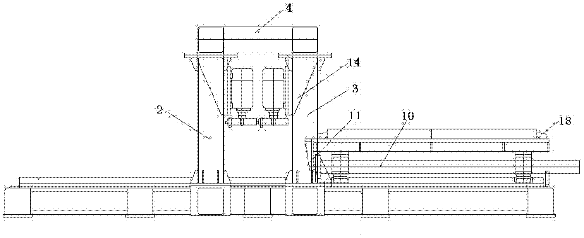
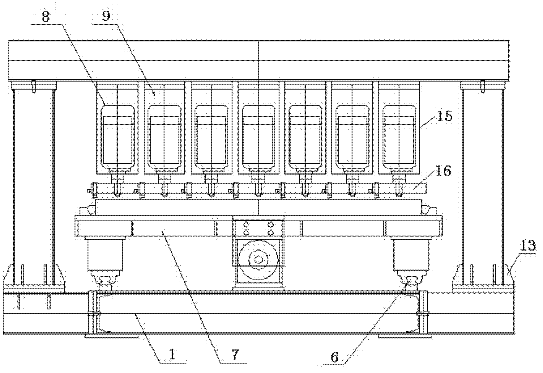
[0019] A multi-milling head gantry milling machine, such as figure 1 , figure 2 As shown, it includes a bed 1, left and right columns 2, 3, and a beam 4. The upper end surface of the bed 1 is provided with a linear slide rail 6, and a worktable 7 is installed on the linear slide rail 6, and a work fixture 18 is provided on the workbench 7, and a positioning bolt is provided on the work fixture 18. Such as Figure 5 As shown, the bottoms of the left and right columns 2, 3 are provided with reinforcing ribs 13 for fixing the left and right columns 2, 3, and the left and right columns 2, 3 are fixed on the column base 19 by bolts. The column base 19 is a square base, and the base is provided with a through hole 17, and the column base 19 is fixed on the bed 1 through the through hole 17. The beam 4 is installed on the left and right columns 2, 3 to form a gantry frame, a first milling head assembly 8 is installed on the beam 4, and a plurality of second milling head assemblie...


PUM


Abstract

The invention relates to a milling machine, in particular to a gantry milling machine with multiple milling heads, which includes a bed, left and right columns, beams, and an electrical control cabinet. The workbench is provided with fixtures, the left and right columns are fixed on the bed, the beam is installed on the left and right columns to form a gantry frame, and the first milling head assembly is installed on the beam. The above-mentioned first milling head assembly is electrically connected with the electrical control cabinet, and a plurality of second milling head assemblies are installed on the beam, and a pushing mechanism for pushing the workbench is arranged on the bed, and the device also It includes an independent driving device that provides power for the pushing mechanism, and the second milling head assembly is electrically connected with the driving device and the electrical control cabinet. The invention can adjust the length of the processing surface according to the size of the product, and also has the advantages of simple structure, low equipment investment, stepless speed regulation, and improved production efficiency.

Description

technical field [0001] The invention relates to a milling machine, in particular to a gantry milling machine with multiple milling heads. Background technique [0002] The gantry milling machine is a milling machine with a portal frame and a long horizontal bed. It has the characteristics of large worktable, strong bearing capacity, and long stroke of the milling head. It is suitable for horizontal planes, vertical planes or inclined planes of large and medium-sized parts on various machines. Groove processing and manufacturing. Now the commonly used equipment for processing filter plates of filter presses is gantry milling machine or disc milling, but there are two problems in processing filter plates with gantry milling machines: (1) CNC gantry milling machines require large equipment investment; (2) ) using ordinary gantry milling machine, the processing time is long and the efficiency is low. And the general gantry milling machine has only one milling head, and the exi...

Claims


Application Information

Patent Timeline
IPC IPC(8): B23C3/13B23Q5/22B23C9/00
Inventor 孙雪虹
Owner 杭州宏邦压滤机制造有限公司
Learn More