A feeding tray of an automatic feeding device

A technology of automatic feeding and feeding, which is applied to vibrating conveyors, conveyors, conveyor objects, etc., can solve problems such as the inability to guarantee the quality of the insertion shaft of the plastic casing motor cover, different insertion depths, and loose shafts, etc. To achieve the effect of reasonable structure design, reduce labor and improve work efficiency

Inactive Publication Date: 2011-12-14
GUANGDONG GALANZ GRP CO LTD
View PDF6 Cites 27 Cited by
  • Summary
  • Abstract
  • Description
  • Claims
  • Application Information

AI Technical Summary

Problems solved by technology

The traditional operation method is to manually insert the shaft rod into the cover plate of the plastic case motor, and press the shaft rod hard, which requires a lot of workers to work by hand. This operation method greatly increases the cost of labor, and cannot guarantee the plastic The quality of the shell motor cover inserting the shaft often has problems such as loose shafts and different insertion depths. To solve the problems, people hope to develop an

Method used


Image

  • A feeding tray of an automatic feeding device
  • A feeding tray of an automatic feeding device
  • A feeding tray of an automatic feeding device

Examples


Embodiment Construction

[0017] The invention will be described in further detail below in conjunction with the accompanying drawings.

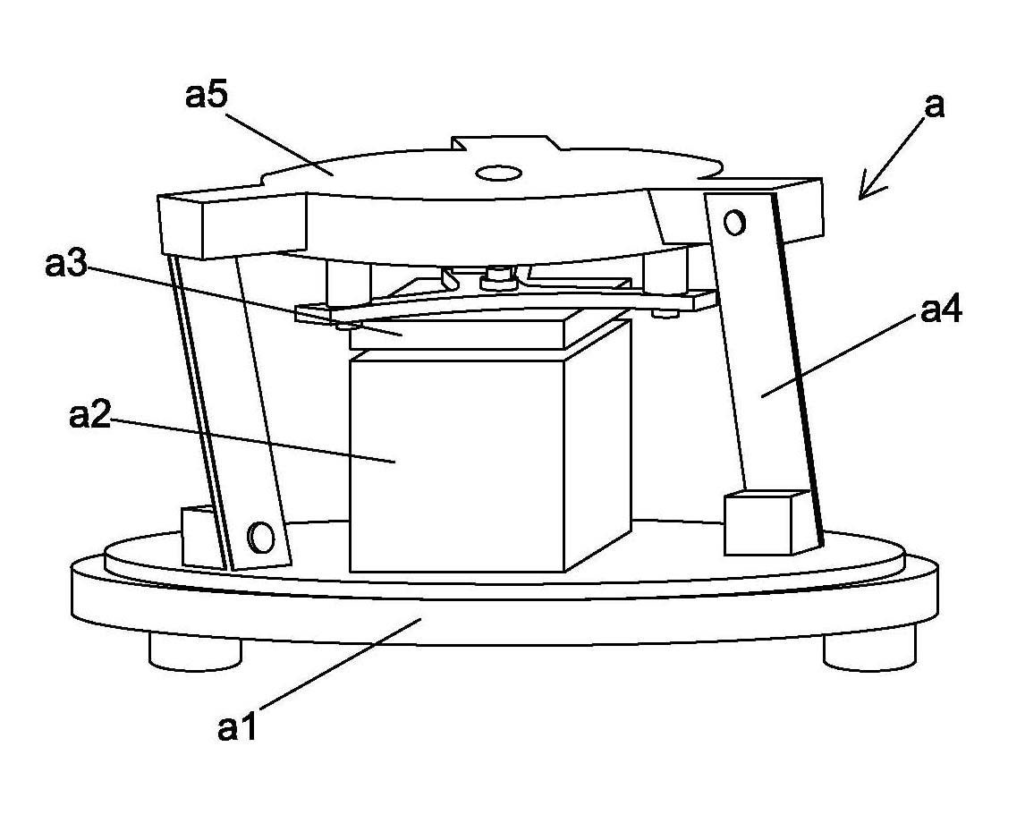
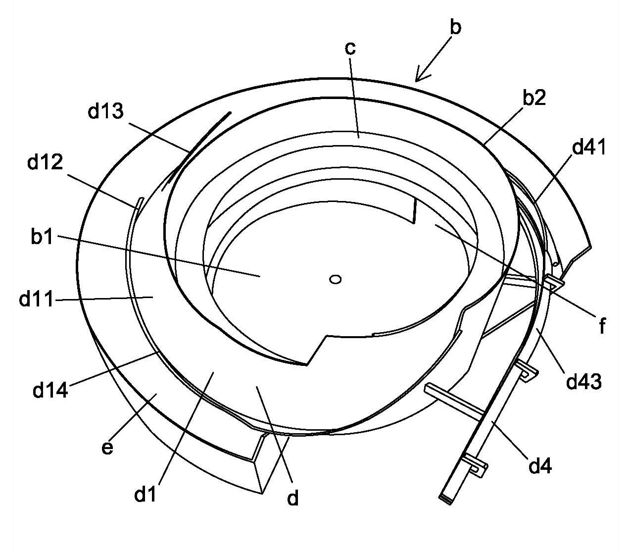
[0018] Such as figure 1 and Figure 5 As shown, a tray of an automatic feeding device is mainly used for an automatic feeding device for the cover plate of a plastic case motor of a microwave oven, including a magnetic vibration host a and a tray b.

[0019] Such as figure 1 As shown: the magnetic vibration host a includes a machine base a1, an electromagnet a2, an armature a3, a vibrating leaf spring a4 and a top seat a5, the electromagnet a2 is installed on the machine base a1, and the armature a3 is installed on the bottom surface of the top seat a5 Above the electromagnet a2, the top seat a5 is suspended above the machine base a1 through more than two vibrating leaf springs a4, and the armature a3 is kept at a certain distance from the electromagnet a2, and the vibrating leaf spring a4 is arranged obliquely; the vibrating leaf spring a4 The angle of inclinatio...


PUM


Abstract

The invention relates to a feeding tray of an automatic feeding device, which comprises a tray surface and a side wall surrounding the tray surface. In the lower part of the disk surface, a monolithic material track is arranged on the outer side of the side wall. The discharge end of the feeding track is connected to the monolithic material track. The monolithic material track includes at least an arrangement section, a turning section, a sorting section and a sorting section. The invention has a reasonable structural design, realizes the automatic distribution of the cover plate of the plastic casing motor, reduces a lot of labor, improves the working efficiency and has the advantages of reducing the production cost.

Description

technical field [0001] The invention relates to an automatic production of microwave oven spare parts, in particular to a feeding tray of an automatic feeding device for microwave oven spare parts. Background technique [0002] Spare parts for microwave ovens, such as the plastic case motor cover, need to insert a shaft into the plastic case motor cover during processing. The traditional operation method is to manually insert the shaft rod into the cover plate of the plastic case motor, and press the shaft rod hard, which requires a lot of workers to work by hand. This operation method greatly increases the cost of labor, and cannot guarantee the plastic The quality of the shell motor cover inserting the shaft often has problems such as loose shafts and different insertion depths. To solve the problems, people hope to develop an automatic shaft insertion machine, which can carry out automated production, reduce labor costs and improve product quality; When developing the au...

Claims


Application Information

Patent Timeline
IPC IPC(8): B65G27/02B65G27/24B65G47/248B65G47/26
Inventor 刘洪彬杨陆军
Owner GUANGDONG GALANZ GRP CO LTD
Why Eureka
Try Eureka