Vacuum light well point dewatering method

A light well point and vacuum technology, applied in drainage, earthwork drilling, safety devices, etc., to achieve strong operability, simple installation, and good precipitation effect

Inactive Publication Date: 2011-12-14
ERCHU CO LTD OF CHINA RAILWAY TUNNEL GRP
View PDF6 Cites 23 Cited by
  • Summary
  • Abstract
  • Description
  • Claims
  • Application Information

AI Technical Summary

Problems solved by technology

How to ensure the best effect of dewatering is the direction of continuous improvement and research in construction, and the application of vacuum light well point dewatering technology in tunnels has few similar successful cases in China

Method used


Image

  • Vacuum light well point dewatering method
  • Vacuum light well point dewatering method
  • Vacuum light well point dewatering method

Examples


Embodiment Construction

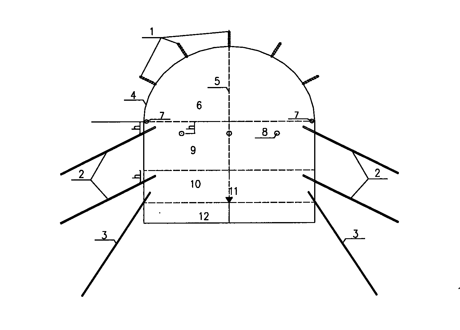
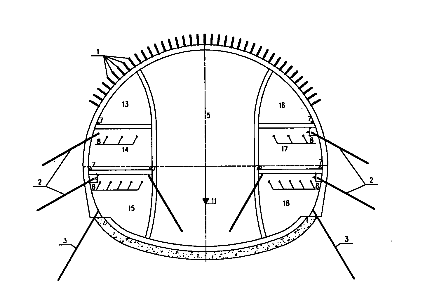
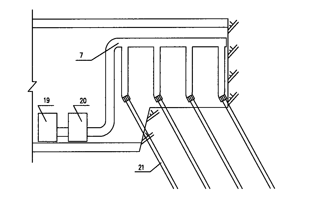
[0034] Next, take the 50.7m inclined shaft and the 505m main tunnel construction project left over from the previous construction in the 4# inclined shaft of the Lanzhou-Chongqing Railway Taoshuping Tunnel undertaken by the applicant as an example to introduce the vacuum light well point dewatering method of the present application. The angles, distances, lengths, number of downcomers and material selection involved are all determined according to the actual situation of the specific project and combined with common sense in the field. Those skilled in the art should know that these angles, distances, lengths, number of downwater pipes and material selection are not limited to those described here, and appropriate selections can be made according to actual engineering needs to achieve a good precipitation effect.

[0035] For details on the layout of downpipes in inclined shafts, see figure 1 , see the layout of the downwater pipes in the construction of the double side walls ...


PUM


Abstract

The invention provides a vacuum lightweight well-point dewatering method, which comprises the following steps of: arranging at least one row of working face advanced vacuum dewatering pipes according to a certain annular interval within a certain angle range of working face vault; excavating an upper step, and arranging at least one row of first vacuum dewatering pipes at a certain distance under the arch foot of the upper step; and excavating an intermediate step, and arranging at least one row of first vacuum dewatering pipes at a certain distance under the arch foot of the intermediate step. The dewatering pipes are arranged according to an excavating working method adopted in tunneling, therefore the method disclosed by the invention has the advantages of simple process, convenience for construction and operation, low energy consumption, low construction cost and good dewatering effect; and the construction equipment is simple to assort, the arrangement of large-scale equipment when other dewatering methods are adopted is reduced, and the construction equipment has the advantages of simpleness in installation, strong operability and convenience for maintenance.

Description

technical field [0001] The invention relates to the application of a vacuum light well point dewatering method in tunnel construction. Background technique [0002] With the development of the national economy, the number of tunnels in railway construction is increasing day by day. In the construction of domestic tunnels, due to the limitation of tunnel selection conditions, individual tunnels must pass through some poor hydrological and geological conditions, which virtually increases the difficulty of tunnel construction. For example, Taoshuping Tunnel, the geological surrounding rock is Tertiary water-rich, weakly cemented silty sandstone, with a permeability coefficient of 8.1×10 -4 cm / s~9.26×10 -4 cm / s, the daily average water inflow in the cave is 570m 3 Above, it is designed as a single-hole double-lane tunnel with a length of 3225m. The whole tunnel is surrounded by grade VI surrounding rock. The construction is difficult and extremely risky. Precipitation is the...

Claims


Application Information

Patent Timeline
Patent Type & Authority Applications(China)
IPC IPC(8): E21F16/02
Inventor 洪开荣李建伟陈庆怀王建军龚天康王雄文李志军王光伟林琳温新亮杨艳玲
Owner ERCHU CO LTD OF CHINA RAILWAY TUNNEL GRP
Why Eureka
Try Eureka