screw compressor

A screw compressor, screw technology, applied in the direction of rotary piston machinery, mechanical equipment, machine/engine, etc., can solve problems such as unrealistic, and achieve the effect of improving vibration attenuation and vibration reduction

Active Publication Date: 2011-12-14
코벨코컴프레서가부시키가이샤
View PDF6 Cites 4 Cited by
  • Summary
  • Abstract
  • Description
  • Claims
  • Application Information

AI Technical Summary

Problems solved by technology

[0011] Therefore, it is considered that by reducing the spring constant of the fixing piece, the natural vibration frequency of the screw compressor is reduced, but in the case of the above example, if the spring constant of the fixing piece is not reduced to 1×10 5 N / m, it would not be within the allowable range relative to the weight of the screw compressor, so it is unrealistic

Method used


Image

  • screw compressor
  • screw compressor
  • screw compressor

Examples


no. 1 approach

[0055] (Structure of screw compressor)

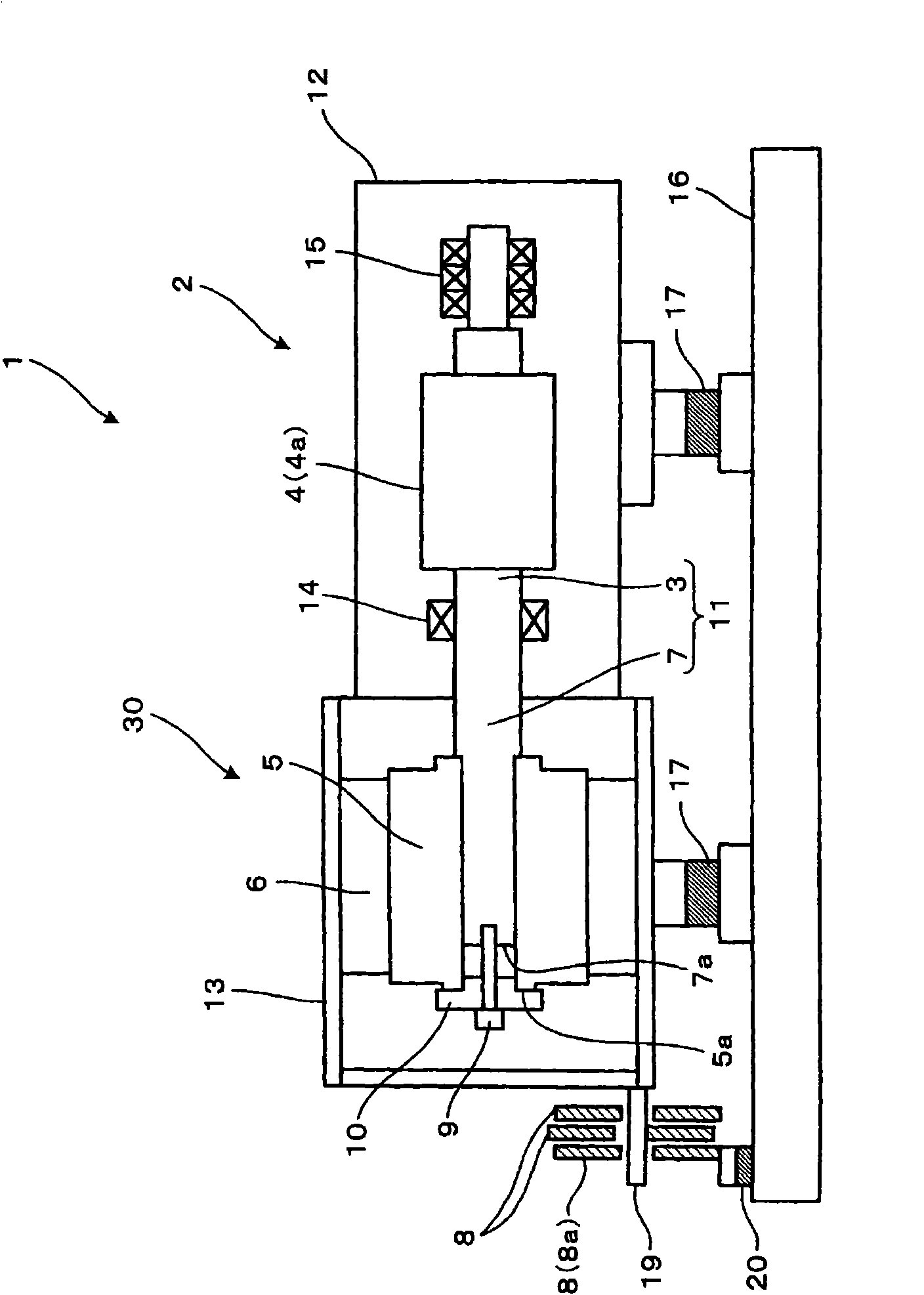
[0056] Such as figure 1 As shown, the screw compressor 1 is a screw compressor of a direct-motor connection structure including a screw body part 2 and a motor part 30 (motor).

[0057] (Screw body part)

[0058] The screw body part 2 has: a pair of male and female screw rotors 4, a screw shaft 3 that is coaxial with the male rotor 4a of the screw rotor 4 and is integrally formed with respect to the male rotor 4a, and a screw housing that accommodates the screw rotor 4 and the screw shaft 3 Body 12. Screw shaft 3 is supported by bearing 14 and bearing 15 two ends.

[0059] The male rotor 4a of the screw rotor 4 and the screw shaft 3 are produced by cutting or the like from a single steel material. It should be noted that the male rotor 4 a and the screw shaft 3 may be separately manufactured and rigidly connected (integrated connection). In addition, the screw shaft 3 and the motor shaft 7 to be described later are also manufacture...

no. 2 approach

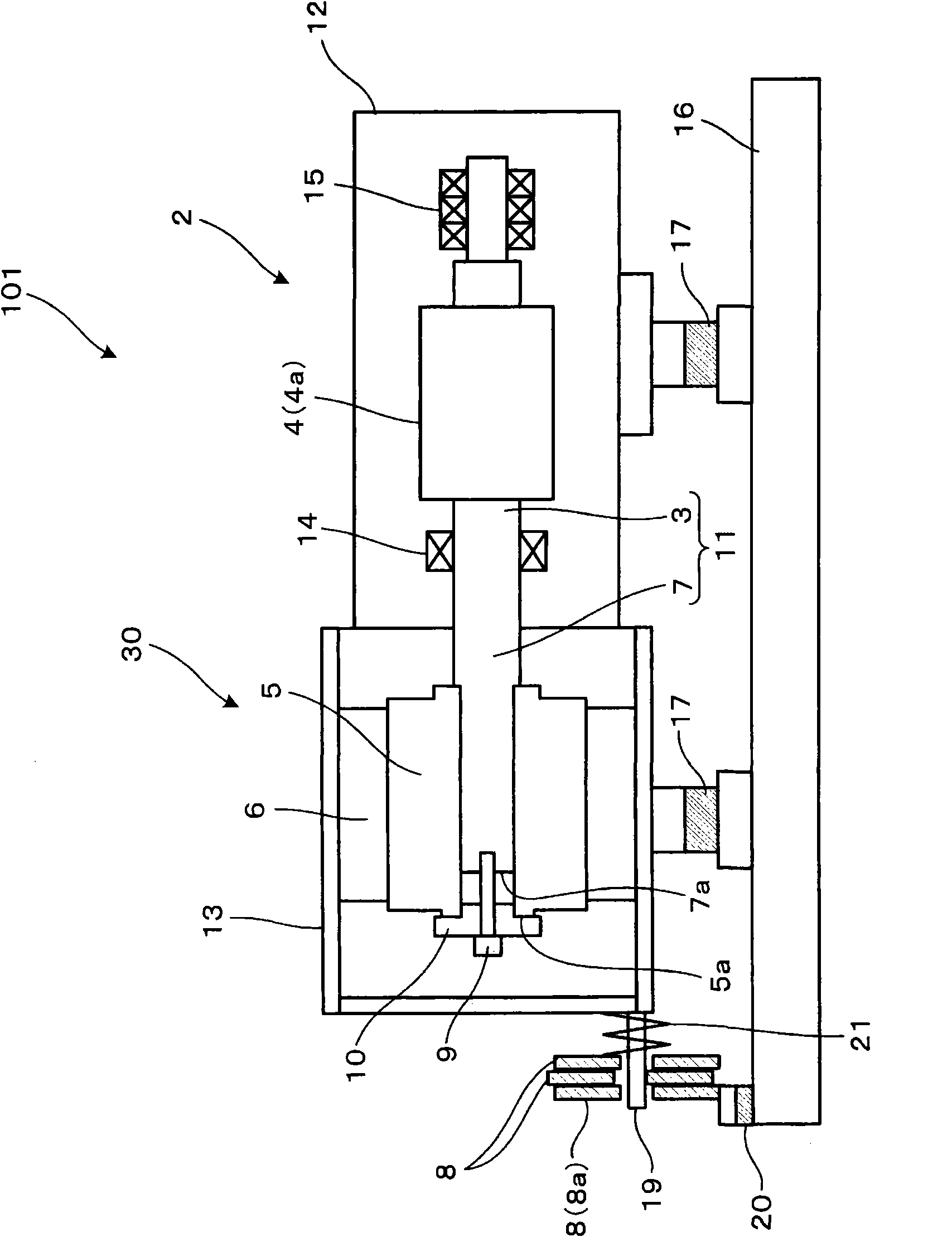
[0078] Next, a screw compressor 101 according to a second embodiment of the present invention will be described. The main differences between the screw compressor 1 of the first embodiment and the screw compressor 101 of this embodiment are: figure 2 As shown, the screw compressor 101 of the present embodiment includes a coil-shaped spring 21 .

[0079] (spring)

[0080] The spring 21 is arranged between the motor housing 13 and the weight 8 that is closest to the motor housing 13 and is not combined with the frame 16 . And, the spring 21 presses the two weights 8 not combined with the machine base 16 to the weight 8a combined with the machine base 16 respectively, wherein the two weights 8 not combined with the machine base 16 are located between the motor housing 13 and the most Between the weight 8a that is far away from the motor housing 13 and combined with the machine base 16 . The weights 8 are in close contact with each other by the spring 21 , and the two weights ...


PUM


Abstract

The invention provides a screw type compressor, which is capable of improving vibration attenuation. A rod-shaped member (19) loosely inserted into a plurality of heavy hammers (8) is equipped on a motor shell (13) in a projecting way. At least one of the multiple heavy hammers (8) is combined with a frame (16). And at least one of the multiple heavy hammers (8) is not combined with the frame (16). When the motor shell (13) is vibrating, the rod-shaped member (19) collides with the heavy hammers so as to disperse the vibration energy. Furthermore, relative displacement which is suitably present between the heavy hammer (8a) combined with the frame (16) and another heavy hammer (8) not combined with the frame in a low-amplitude area leads to sliding friction between the above two heavy hammers. The vibration energy is thus further dispersed.

Description

technical field [0001] The present invention relates to screw compressors. Background technique [0002] The screw compressor with the direct connection structure of the motor has better energy conversion efficiency than the screw compressor with the power transmission method through the drive belt. Furthermore, among the screw compressors adopting the rotational speed control method using an inverter, the screw compressors having a motor direct connection structure are becoming mainstream. Therefore, for the purpose of cost reduction and reduction of mechanical loss, a single-side support type screw compressor with no bearing provided on one side of the motor shaft is widely used. [0003] In the motor direct connection type screw compressor with one-sided support, since the motor with a large mass is supported on one side, it is difficult to obtain a large bending rigidity of the rotor shaft, which is the integrated structure of the motor shaft and the screw shaft. The p...

Claims


Application Information

Patent Timeline
Patent Type & Authority Applications(China)
IPC IPC(8): F04C18/16
Inventor 上田宏树黑田健志星川明
Owner 코벨코컴프레서가부시키가이샤
Why Eureka
Try Eureka