
Flexible toothbrush head

a flexible, toothbrush head technology, applied in the field of toothbrushes, can solve the problems of a toothbrush with a very rigid head that cannot be easily conformed to the physical characteristics of a user, and achieve the effect of improving the physical characteristics of the user

Active Publication Date: 2005-03-31
COLGATE PALMOLIVE CO
View PDF14 Cites 10 Cited by
  • Summary
  • Abstract
  • Description
  • Claims
  • Application Information

AI Technical Summary

Benefits of technology

[0009] To improve a user's overall brushing experience, the inventors of the present invention have determined a softer, flexible head would be desired for use by a user. Such a head would flex under normal brushing conditions. The above AFT process could still be used to fix the relative positions of the bristles, and therefore provide a commercially appealing toothbrush. However, the inventors of the present invention have determined that such a head plate formed of elastomeric material is unable to be sonically welded to the head portion of the handle. This is because the elastomeric material absorbs and dissipates the vibrational energy imparted to the head plate during sonic welding.
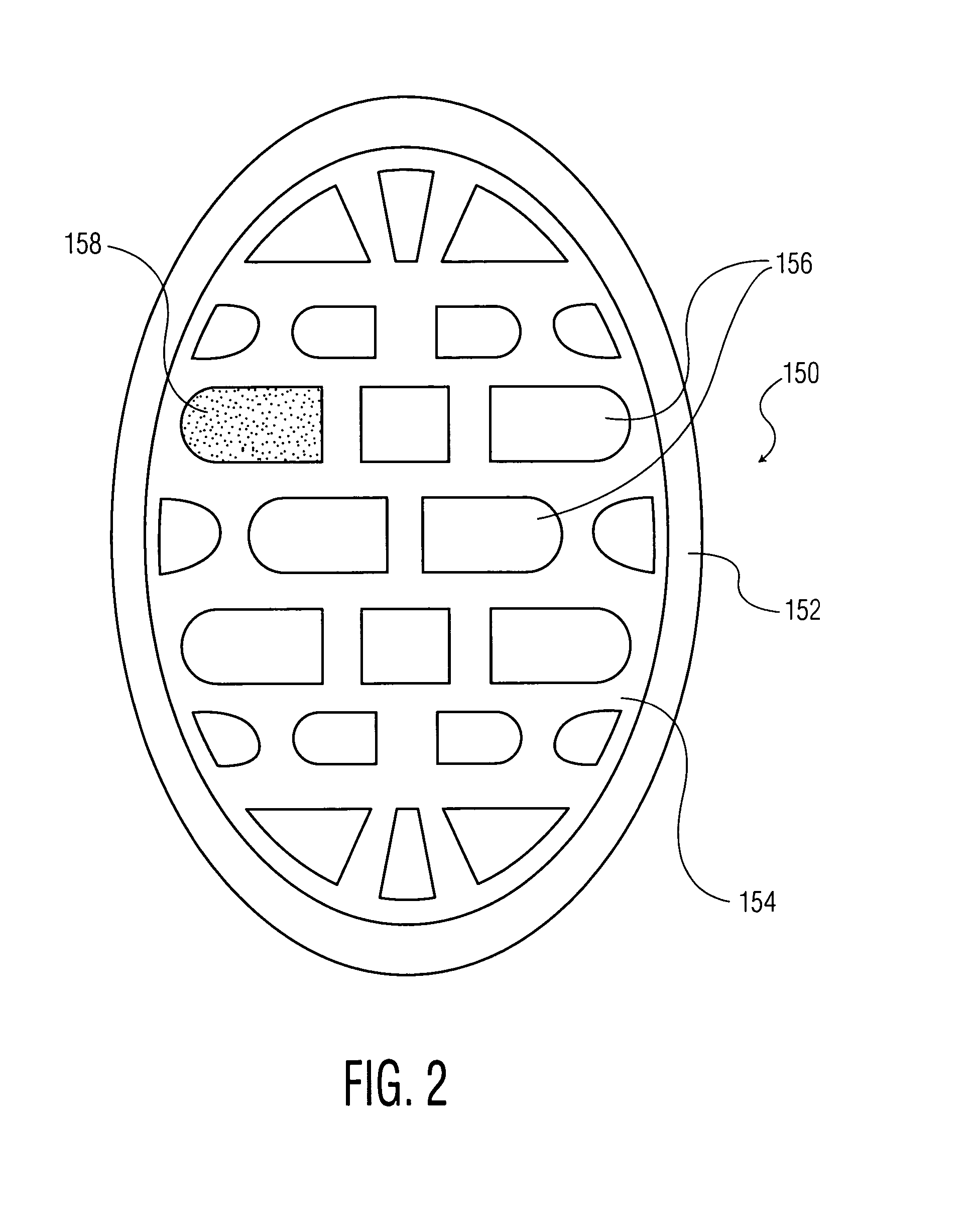
[0010] Therefore, in order to overcome this drawback, the present invention is directed to a head plate for a toothbrush formed of two materials. A first rigid material is used to form the perimeter portion of the head plate. Such a material, such as for example polypropylene, is easily sonically welded. The tuft field is formed of a flexible elastomer (preferably having a hardness of 90 Shore A or less) that allows the field, and therefore the head plate and bristles to move or flex under the pressure of normal brushing. Thus, such a head plate is able to flex, thus allowing the tuft field and bristles to move under normal brushing conditions, while providing a perimeter of structural rigidity that is able to be sonically welded.
[0011] According to another embodiment of the present invention, a method for forming a head for use with a toothbrush is provided, comprising the steps of forming an outer perimeter portion of a rigid material, said rigid material being adapted to allow said head to be sonically welded; positioning a tuft field within said outer perimeter portion, said tuft field being formed of a flexible elastomer, said tuft field defining one or more apertures to receive one or more bristle tufts; placing a bristle tuft within at least one corresponding aperture in said tuft field; melting a portion of bristles in said bristle tuft to secure said bristle tuft in said aperture in said tuft field; and sonically welding said tuft field into place in said toothbrush.

Problems solved by technology

However, this manufacturing process results in a toothbrush with a very rigid head that does not easily conform to the physical characteristics of a user when brushing.

Method used


Image

  • Flexible toothbrush head
  • Flexible toothbrush head
  • Flexible toothbrush head

Examples


Embodiment Construction

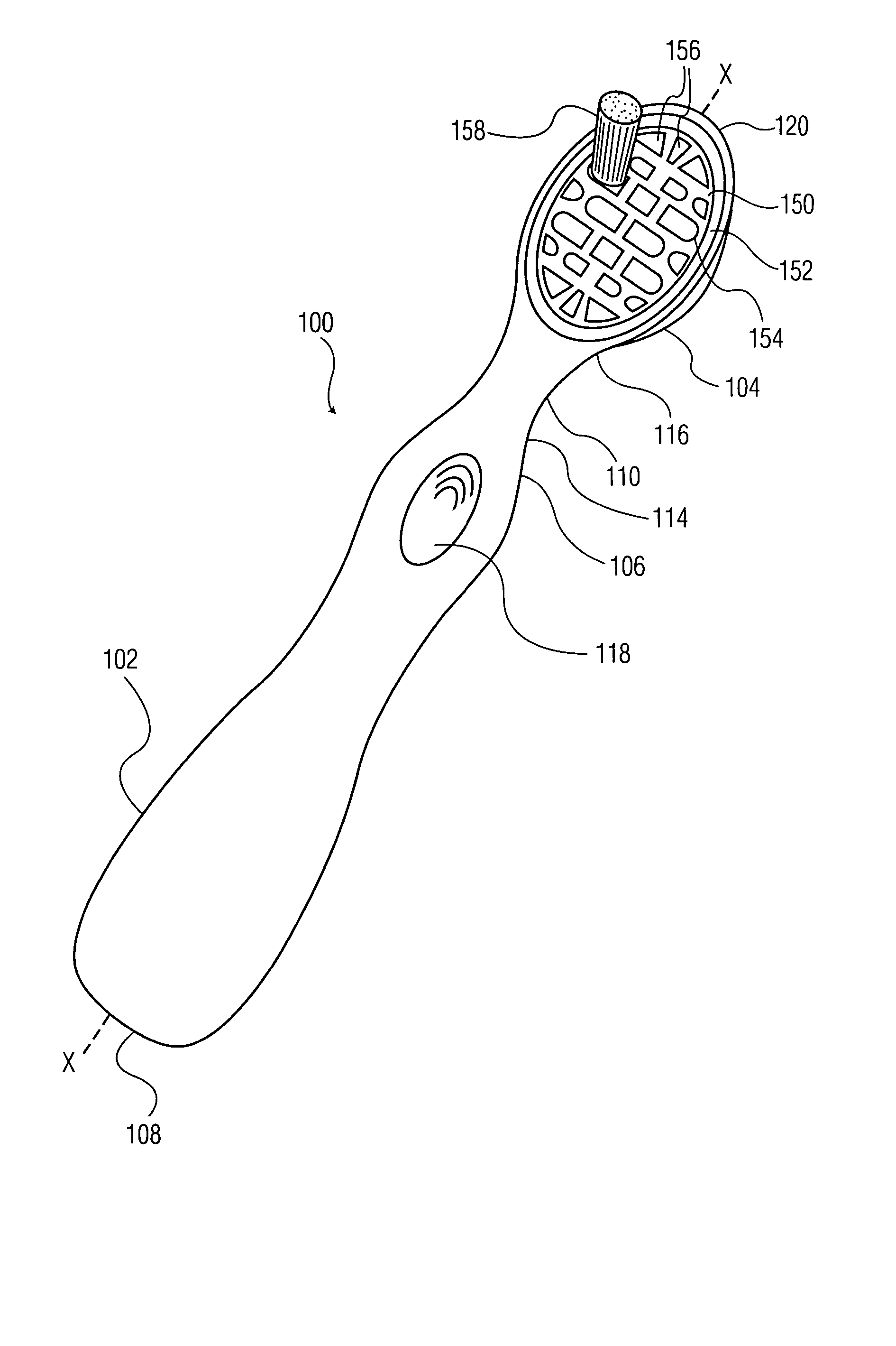
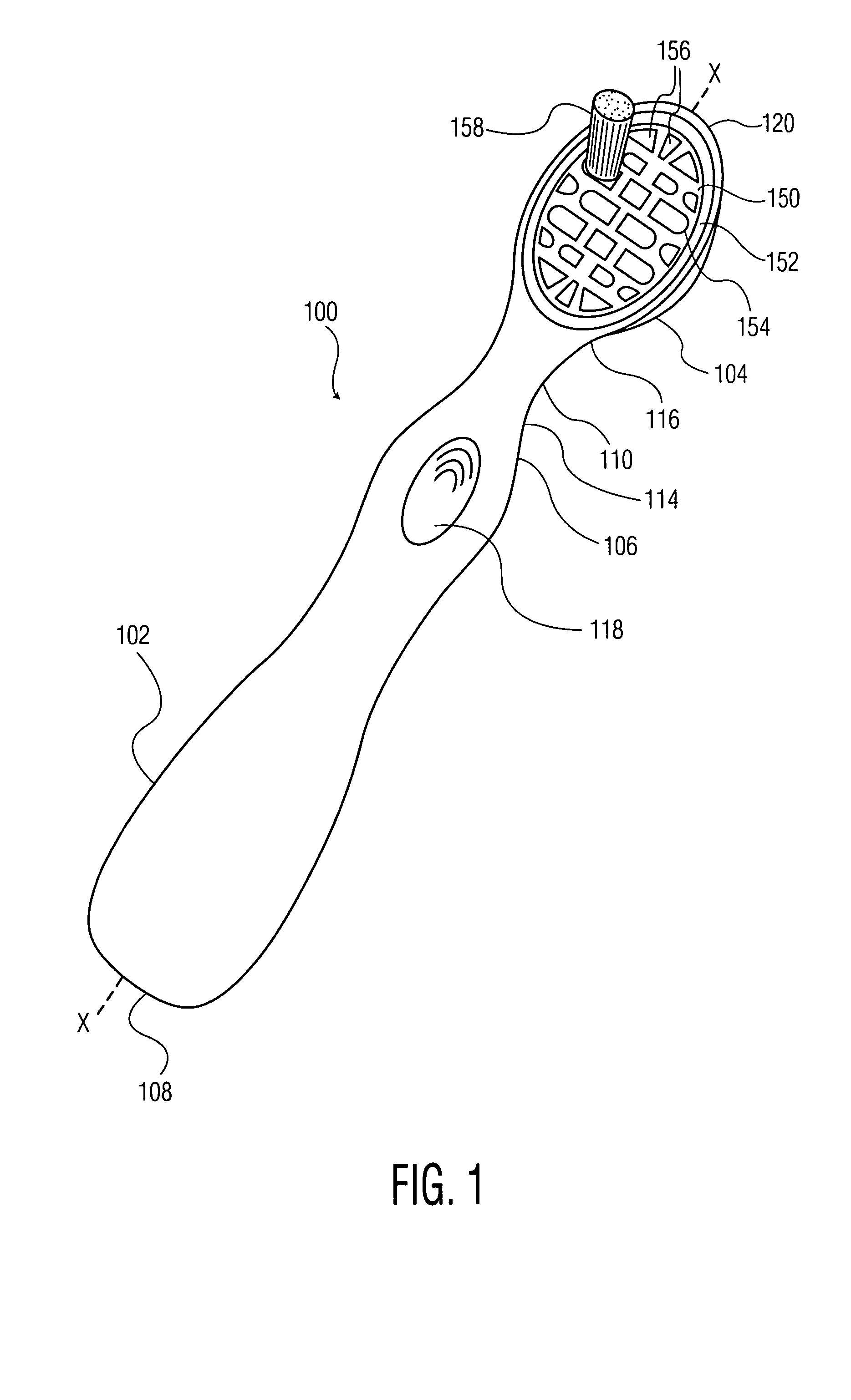
[0017] Referring to FIGS. 1 and 2, an exemplary toothbrush including a head plate according to the invention is illustrated and generally indicated at 100.

[0018] Toothbrush 100 includes a handle 102 at a proximal end thereof, and a brush section 104 that is defined by a neck 110 that terminates in a head 120 at a distal end of toothbrush 100. Handle 102 has a free proximal end 108 and an opposite neck end 106. Neck 110 generally includes a first end 114 and a second end 116 with first end 114 being located at neck end 106 of handle 102 and the second end 116 being located at head 120. In other words, neck 110 is the portion of toothbrush 100 that extends between handle 102 and head 120. Head 120 is preferably generally aligned with the longitudinal axis x-x of toothbrush 100.

[0019] Neck 110 and handle 102 may be constructed as a unitary member by forming neck 110 integral to handle 102 at neck end 106 of handle 102, or may be formed detachable from handle 102 at the neck end 106. ...


PUM


Abstract

A head for use with a toothbrush and method for forming the same, comprising an outer perimeter portion formed of a rigid material. The rigid material is adapted to allow the head to be sonically welded. The head also comprises a tuft field positioned within the outer perimeter portion. The tuft field is formed of a flexible elastomer. The tuft field defines one or more apertures to receive one or more bristle tufts. The head is sonically welded into place in the toothbrush.

Description

BACKGROUND OF THE INVENTION [0001] 1. Field of the Invention [0002] The present invention relates to toothbrushes, and more particularly, to a toothbrush being formed using an Anchor Free Tufting (AFT) process. [0003] 2. Discussion of Related Art [0004] Toothbrushes provide many oral hygiene benefits. For example, toothbrushes remove plaque and food debris to help avoid tooth decay and disease. They remove stained pellicle from the surface of each tooth to help whiten the teeth. Also, the bristles combined with the brushing motion massage the gingival tissue for stimulation and increased health of the tissue. [0005] A toothbrush head should provide both proper support for the bristles, and be flexible enough during use to allow the bristles to conform to the shape of a user's mouth or teeth. Additionally, construction techniques should be inexpensive, versatile and consistent. [0006] In an attempt to meet these criteria, a process known as “Anchor Free Tufting” (“AFT”) has been used...

Claims


Application Information

Patent Timeline
Patent Type & Authority Applications(United States)
IPC IPC(8): A46B7/06A46B9/04
CPCA46B3/20A46B2200/1066A46B7/06A46B5/0025
Inventor MOSKOVICH, ROBERT A.ROONEY, MICHAEL C.
Owner COLGATE PALMOLIVE CO
Learn More