
Electric tool control circuit and its operation method

A technology of electric tools and control circuits, which is applied in the direction of measuring electricity, measuring electric variables, measuring devices, etc., which can solve the problems of users such as danger, inability to report to the police and stop working in time, and inability to understand the remaining power of the battery pack, etc., to achieve discharge work Safe and accurate indication

Inactive Publication Date: 2011-12-14
NANJING CHERVON IND
View PDF2 Cites 6 Cited by
  • Summary
  • Abstract
  • Description
  • Claims
  • Application Information

AI Technical Summary

Problems solved by technology

[0005] This detection and indication method makes it impossible for the user to know the remaining power of the battery pack once the electric tool starts to work. At the same time, due to the no longer monitoring of other parameters of the battery pack, once the battery pack is over-current or over-temperature, it is impossible to report in time. and stop working, posing a danger to the user

Method used


Image

  • Electric tool control circuit and its operation method
  • Electric tool control circuit and its operation method
  • Electric tool control circuit and its operation method

Examples


Embodiment Construction

[0020] specific implementation plan

[0021] The present invention will be described in detail below in conjunction with the accompanying drawings and specific embodiments.

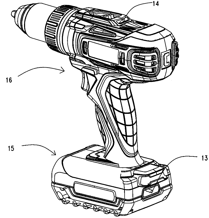
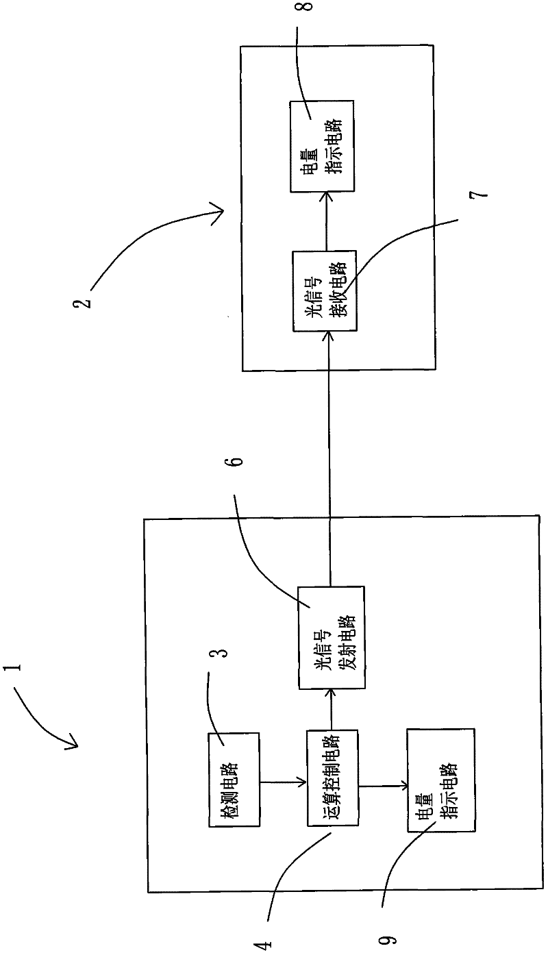
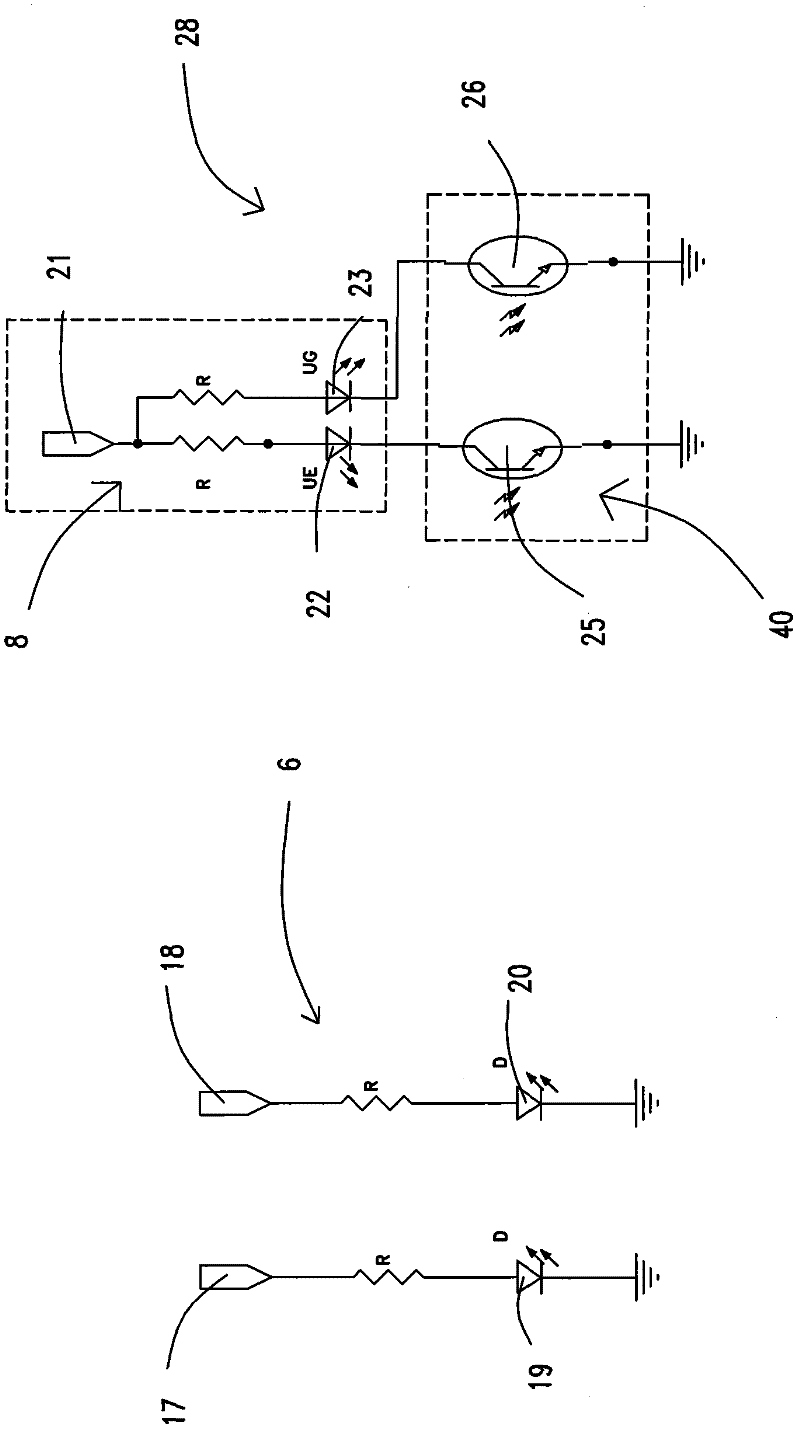
[0022] DC power tools, under normal working conditions, include a motor installed in the casing, a switch, and a battery pack containing multiple rechargeable batteries. Both the fuselage and the battery pack are equipped with a power indicating device for displaying the power condition of the battery pack. Take the electric drill as an example, such as figure 1 As shown, the fuselage 16 and the battery pack 15 of the electric drill are equipped with power indicating devices, wherein the fuselage power indicating device 14 is installed on the top of the fuselage 16 , and the battery pack power indicating device 13 is installed on the rear side of the battery pack 15 . The battery pack power indicating device 13 and the fuselage power indicating device 14 are preferably red and green dual-color LED light...


PUM


Abstract

A control circuit of an electric tool and an operation method thereof. The electric tool control circuit includes a battery pack detection circuit, an operation control circuit, an electric power indicator circuit for displaying the electric power calculation result, and a current measurement circuit for measuring the current I flowing through the motor, wherein the electric power calculation result of the operation control circuit also includes the battery The voltage consumed inside the package and the circuit. The method of operating the electric tool includes pressing a switch to electrically connect the motor to the battery, measuring the parameters of the battery, and thereby controlling the operation or stop of the motor. After the motor is running, the power calculation is performed, and the power calculation result is displayed on the power indicating device show.

Description

[0001] This application is a divisional application of the Chinese application with the application number 201010204598.8, the application date is June 11, 2010, and the title is "electric tool power display". technical field [0002] The invention relates to a control circuit of an electric tool and an operation method thereof. Background technique [0003] Generally, DC power tools using battery packs have the function of detecting and indicating the remaining power of the battery pack. In general, the displayed remaining battery capacity is obtained by directly measuring the voltage at both ends of the battery. When the temperature of the battery pack increases due to discharge, the internal resistance also changes accordingly. The measured voltage at this time cannot accurately reflect the actual capacity of the battery. The power supplied to the motor causes deviations in the display of the remaining power. [0004] At the same time, this detection and indication are a...

Claims


Application Information

Patent Timeline
Patent Type & Authority Applications(China)
IPC IPC(8): G01R31/36
Inventor 杨德中耿正
Owner NANJING CHERVON IND
Learn More