Transformer station guiding optical cable optimization laying system

A technology for substations and optical cables, applied in the installation of optical fibers/cables, etc., can solve the problems of heavy optical cable laying workload, shallow pre-buried depth of optical cables, and excessive optical cables, so as to reduce the workload of optical cable laying, improve the overall reliability, and save energy. The effect of total project investment

Inactive Publication Date: 2013-01-30
ZHEJIANG ELECTRIC POWER DESIGN INST
View PDF0 Cites 0 Cited by
  • Summary
  • Abstract
  • Description
  • Claims
  • Application Information

AI Technical Summary

Problems solved by technology

[0004] 1. The communication room cannot uniformly plan the wiring, which increases the workload of operation and maintenance, which is not conducive to rapid troubleshooting
[0005] 2. A large number of guiding optical cables are laid in stages, and it is necessary to repeat the work of uncovering the cable cover and sealing the fire of the cable trench, and the workload of laying optical cables is heavy
[0006] 3. In the later stage of guiding optical cable laying project, it is easy to have shallow embedded depth of optical cable and substandard safety protection measures, which reduces the reliability of optical cable line
[0007] 4. There are too many optical cables laid in the cable trench, which requires high safety measures such as fire prevention

Method used


Image

  • Transformer station guiding optical cable optimization laying system
  • Transformer station guiding optical cable optimization laying system
  • Transformer station guiding optical cable optimization laying system

Examples


example 1

[0028] Example 1: Typical scale 500kV substation

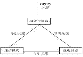
[0029] Substation final output scale: 10 circuits for 500kV lines and 12 circuits for 220kV lines. OPGW optical cable construction is based on 500kV lines with 2 circuits and 1 cable, and 220kV lines with 2 circuits and 1 cable. Before adopting the optimal laying system of substation guide cables, there are 15 guide cables for 500kV OPGW and 18 guide cables for 220kV OPGW. Please refer to Attached Table 1 for details about the laying of guide cables. Please refer to Attachment for the connection diagram of 220kV OPGW guide cables. Figure 7 .

[0030] Attached table 1 Typical 500kV substation guide cable laying table

[0031]

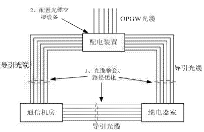
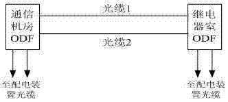
[0032] After adopting the optimized laying system of the substation guide optical cable (take the 220kV part as an example), use a large-core optical cable, set up a reasonable optical cable access convergence point, and configure an optical cable transfer box, and integrate the optical cables ...


PUM


Abstract

The invention provides a transformer station guiding optical cable optimization laying system which comprises a communication machine room and a relay house. Two multi-core guide optical cables connect the communication machine room with the relay rouse. The guide optical cables are installed in conduits through two cable grooves or pipes with different paths, and get in and out the communication machine room and the relay house through two different cable holes. The communication machine room and the relay house connect with a specially configured power distribution unit through the guide optical cables, and get OPGW (Optical Fiber Ground Wire Cable) external connection through the power distribution unit. The power distribution unit is an intersection unit of cable configuration. A power distribution area is provided with a set of optical cable intersection box which is arranged at an outlet interval middle position and near the cable grooves, and the optical cable intersection box is used for cable distribution and splice between cables from an optical cable splice box direction and cables from communication machine room and relay house directions, wherein the cable splice employs a welding mode. The transformer station guiding optical cable optimization laying system has the characteristics of improvement of overall reliability of an optical cable line, simplification of operation work, and reduction of optical cable laying workload to achieve a scientific, reasonable and reliable effect and the like.

Description

technical field [0001] The invention relates to a new type of guiding optical cable laying system in a substation, which belongs to the optical cable network system of a power communication network, and mainly provides a more efficient and reliable technical solution for laying and connecting guiding optical cables in a substation. technical background [0002] With the development of communication technology, optical fiber communication has become the main communication mode of power communication network, and OPGW optical cable has become the main type of optical cable of power communication network. At the same time, combined with the need for line protection fiber optics, the construction of OPGW optical cables has grown rapidly. At present, the laying of guiding optical cables in substations mainly adopts the delta connection method, such as figure 1 As shown, that is, the frame optical cable connection box-communication room-relay room-framework cable connection box, ...

Claims


Application Information

Patent Timeline
Patent Type & Authority Patents(China)
IPC IPC(8): G02B6/46
Inventor 方显业赵萌刘宏波胡映梅毛婕施瑾陈北海
Owner ZHEJIANG ELECTRIC POWER DESIGN INST
Why Eureka
Try Eureka