Check patentability & draft patents in minutes with Patsnap Eureka AI!

Reaction device and method for manufacturing the reaction device

The technology of a reaction device and manufacturing method is applied in the direction of spraying device, measuring device, spraying device, etc., which can solve the problems of cumbersome bonding process, increased etching workload, cumbersome manufacturing process of reaction device, etc.

Active Publication Date: 2011-12-14
KOBELCO ECO-SOLUTIONS CO LTD
View PDF2 Cites 0 Cited by
  • Summary
  • Abstract
  • Description
  • Claims
  • Application Information

AI Technical Summary

Problems solved by technology

[0008] However, to form Figure 11 The flow path structure 132 shown requires etching for forming grooves corresponding to the first introduction path 104, the second introduction path 106, the reaction path 110, and the confluence path 108 on the substrate 112. It is necessary to etch the two sealing plates 114, 116 so that only the part of the two sealing plates 114, 116 corresponding to the reaction path 110 protrudes, resulting in increased etching workload
In addition, it is necessary to perform positional alignment with respect to the substrate 112 and to bond the two sealing plates 114, 116 so that the protruding portions of the two sealing plates 114, 116 are embedded in the substrate 112 etched in the above-mentioned manner. In the part corresponding to the reaction path 110, the bonding process of the sealing plates 114, 116 and the substrate 112 becomes cumbersome.
Therefore, with this structure, there is a problem that the manufacturing process of the reaction device becomes cumbersome.

Method used


Image

  • Reaction device and method for manufacturing the reaction device
  • Reaction device and method for manufacturing the reaction device
  • Reaction device and method for manufacturing the reaction device

Examples


Embodiment Construction

[0025] Hereinafter, embodiments of the present invention will be described with reference to the drawings.

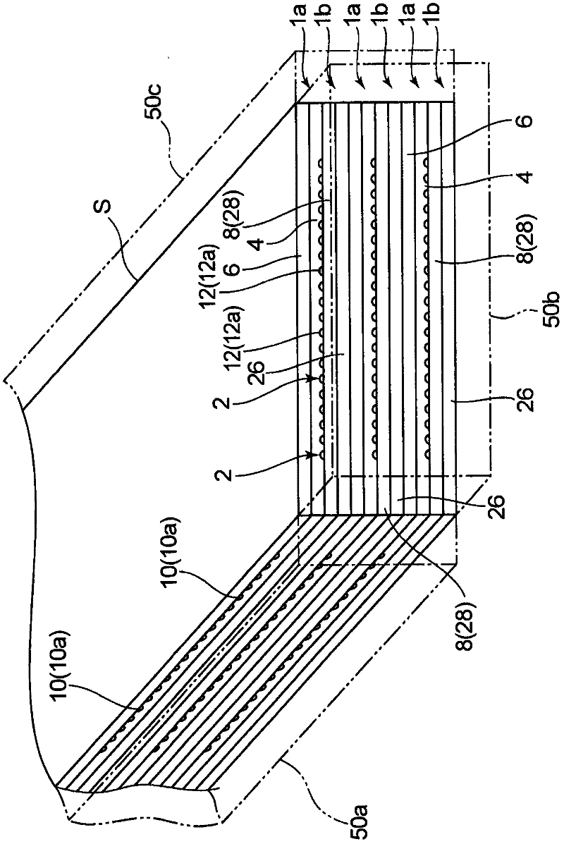
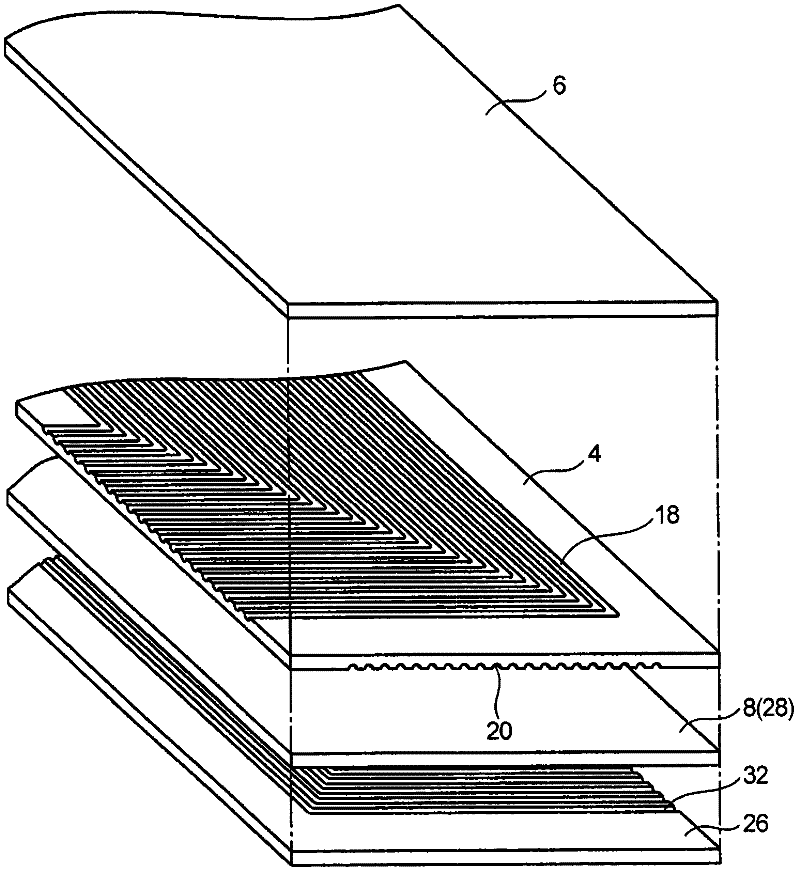
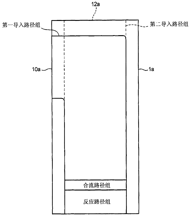
[0026] First, refer to Figure 1 to Figure 9 , the structure of the reaction apparatus according to one embodiment of the present invention will be described.

[0027] The reaction device of this embodiment includes figure 1 The flow path device S shown. In this flow path device S, the first flow path structure 1a having a plurality of flow paths 2 through which a reactant flows and the second flow path structure 1b having a plurality of heat medium flow paths through which a heat medium flows are alternately arranged. It is constructed by stacking multiple layers. In addition, the first flow channel structure 1a among the above two flow channel structures 1a, 1b is included in the concept of the flow channel structure of the present invention.

[0028] In addition, the reaction device of this embodiment is generally called a microreactor (microreactor), and the re...


PUM


Abstract

A reactor comprises a channel forming body internally formed with a channel including a first inlet path, a second inlet path, a junction channel connected with a downstream side of the first inlet path and that of the second inlet path, and a reaction channel connected with a downstream side of the junction channel, wherein: the channel forming body includes a base plate, a first sealing member bonded to one surface of the base plate while covering the one surface, and a second sealing member bonded to other surface of the base plate while covering the other surface; a first inlet groove for forming the first inlet path and a reaction groove for forming the reaction channel are formed in the one surface of the base plate while a second inlet groove for forming the second inlet path is formed in the other surface of the base plate; the base plate is formed with a junction hole for forming the junction channel, the junction hole penetrating the base plate from the one surface to the other surface between the first and second inlet grooves and the reaction groove so as to the interconnect downstream ends of the inlet grooves and an upstream end of the reaction groove; and the reaction groove has a reaction groove connecting portion which is connected with the junction hole and has a depth larger than a depth of a first inlet groove connecting portion of the first inlet groove, the first inlet groove connecting portion connected with the junction hole.

Description

technical field [0001] The present invention relates to a reaction device and a method for manufacturing the reaction device. Background technique [0002] Conventionally, a desired reaction product has been produced by making a first reactant and a second reactant flow while they are in contact with each other and making these two reactants react with each other. The production of such a product uses, for example, a reaction apparatus disclosed in Patent Document 1 below. [0003] Figure 10 and Figure 11 An example of the reaction apparatus disclosed in this patent document 1 is shown in each. [0004] Figure 10 The shown reaction device includes a channel structure 102 in which a channel through which a reactant flows is provided. The flow path in the flow path structure 102 includes: a first introduction path 104 for introducing a first reactant, a second introduction path 106 for introducing a second reactant, and two kinds of reactants flowing through the introduc...

Claims


Application Information

Patent Timeline
Patent Type & Authority Applications(China)
IPC IPC(8): B01J19/00B81B1/00B81C3/00
CPCB01J2219/00783B01J2219/00873B01J19/0093B01J2219/00889B01J2219/00862B01J2219/00891B01J2219/0086B01J19/00B81B1/00B81C3/00
Inventor 吉田龙生野一色公二
Owner KOBELCO ECO-SOLUTIONS CO LTD
Features
  • R&D
  • Intellectual Property
  • Life Sciences
  • Materials
  • Tech Scout
  • Unparalleled Data Quality
  • Higher Quality Content
  • 60% Fewer Hallucinations
Learn More