Method for controlling temperature of hot isobaric press and hot isobaric press

A technology of presses, heat, etc., applied in the field of presses, can solve the problems of reducing heating power, preventing separation, stopping convective flow, etc., to achieve the effect of avoiding temperature changes

Inactive Publication Date: 2014-10-15
克莱默热处理设备公司
View PDF6 Cites 0 Cited by
  • Summary
  • Abstract
  • Description
  • Claims
  • Application Information

AI Technical Summary

Problems solved by technology

The disadvantage is that, on the one hand, sudden cooling with parameters that cannot be reliably controlled can occur, and a uniform cooling rate cannot be achieved throughout the charging area
However, in pressure vessel systems, the heating element acts at the outer surface of the charge zone and thus cannot completely prevent separation inside the charge zone
In the embodiment according to WO 2003 / 070 402 A1, an active convective flow through the charging zone is used in a targeted manner, wherein in the holding phase, for example between a heating phase and a cooling phase or in the case of a step-like temperature change, due to The required heating power is consequently reduced, so that the convective flow virtually stops and therefore the desired effect can no longer be achieved during the holding phase

Method used


Image

  • Method for controlling temperature of hot isobaric press and hot isobaric press
  • Method for controlling temperature of hot isobaric press and hot isobaric press
  • Method for controlling temperature of hot isobaric press and hot isobaric press

Examples


Embodiment Construction

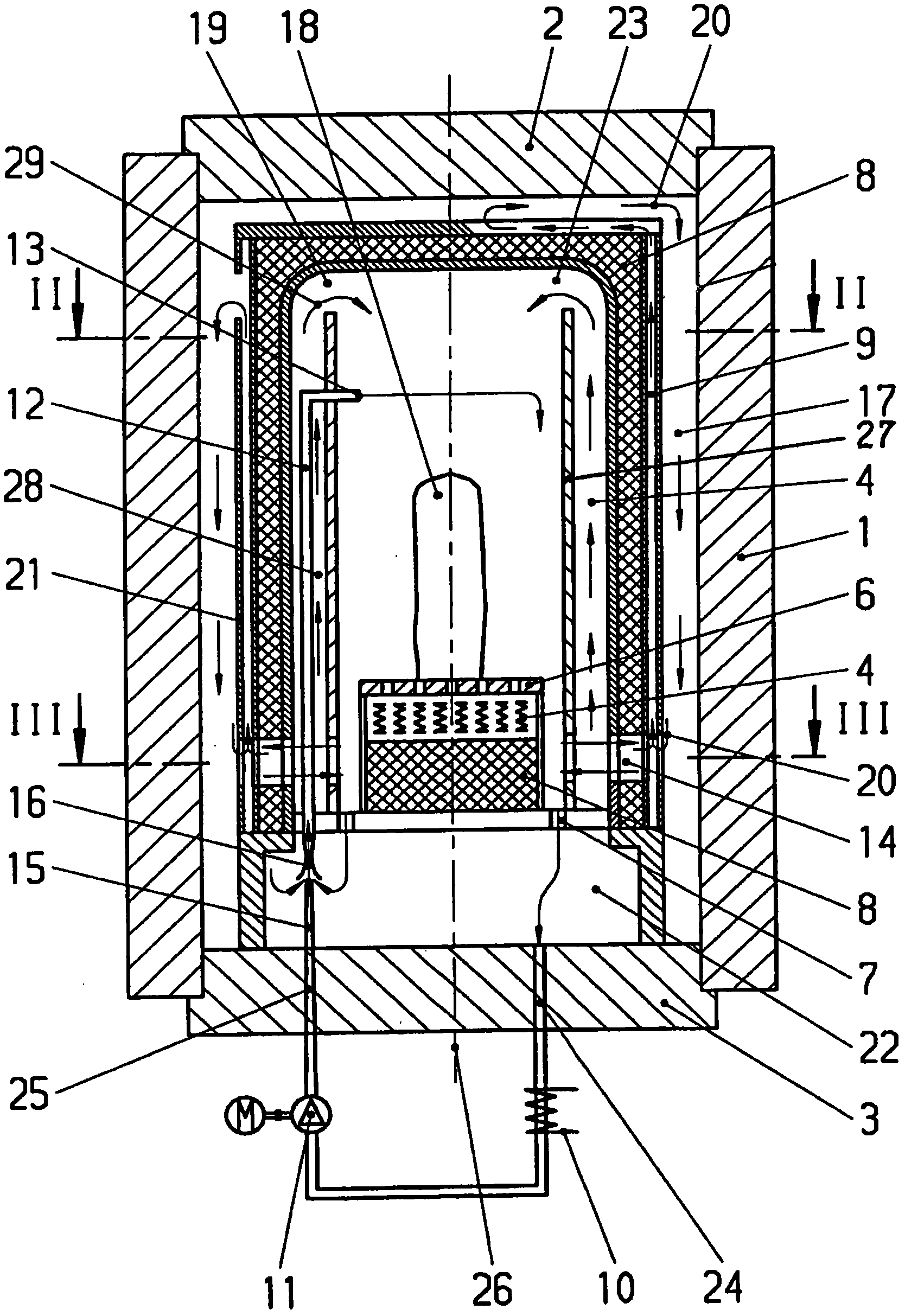
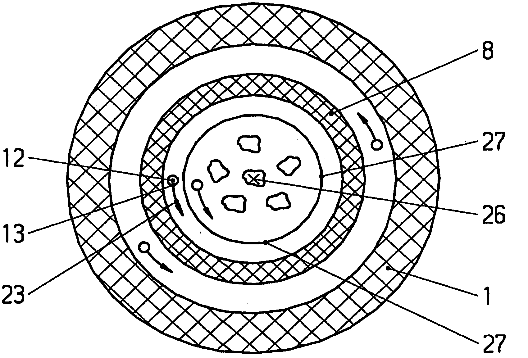
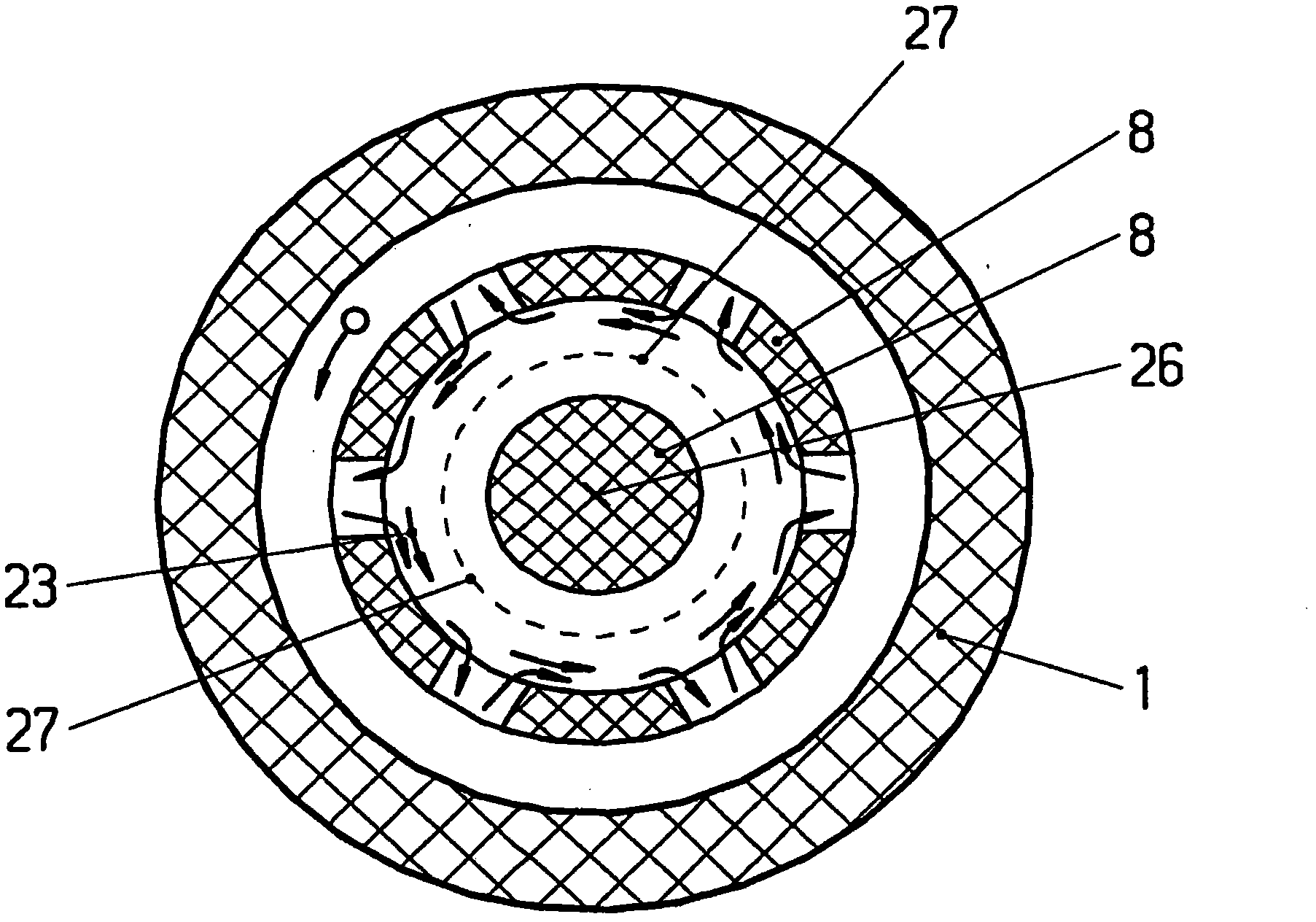
[0023] The pressure vessel 1 shown in the figures has a generally inner charging zone 19 and a thermal insulation 8 arranged between the charging zone 19 and the outer wall of the pressure vessel 1 . In order to form the convection gap 28 , a convection sleeve 27 is arranged in the filling area 19 . The cooling of the pressure vessel 1 as described is explained below. Active heating with a heated fluid or with the aid of heating elements is expedient. Furthermore, within the insulation 8 there is a heating element 4 and a charging device 18 is usually arranged on the charging support plate 6 or, in the case of blocks, by means of a material support (not shown) on the charging support plate 6 . The pressure vessel 1 also has closing caps 2 and 3 which can be used for charging and discharging the pressure vessel 1 , but for the sake of simplicity of description, these are considered to be part of the pressure vessel 1 in the following. Inside the insulator 8 , in the charging ...


PUM


Abstract

A method for controlling the temperature of a hot isobaric press and a hot isobaric press comprising a pressure vessel (1) with a charging zone (19) located inside and arranged in An insulator (8) between the charging area and the pressure vessel, wherein a heating element (4) and a charging area (19) with a charging device (18) are arranged inside the insulating body (8), wherein for Forming a convection gap (28), at least the charging zone (19) is surrounded by a convection jacket (27), wherein fluid is injected via at least one nozzle (13) inside the pressure vessel (1) and / or the charging zone (19) to A swirl (23) is formed and this fluid mixes with the fluid there, and at the same time this fluid constitutes a circulation circuit (29) around said convection jacket (27) and enters said charging zone from said convection gap (28) (19). A hot isobaric press, wherein at least one conduit (12) is arranged in the pressure vessel (1) connected to at least one nozzle (13) inside the pressure vessel (1), wherein the exit angle of the nozzle (13) is suitable for A swirling flow (23) is formed in the charging zone (19) and conduits (12) are connected to regions of the pressure vessel (1) at different temperatures.

Description

technical field [0001] The invention relates to a method for controlling the temperature of a hot isobaric press according to the preamble of claim 1 and a hot isobaric press according to the preamble of claim 12 . Background technique [0002] Hot isobaric presses (HIP) or high pressure boilers are used today in a wide range of applications. Here, solid workpieces or molding materials made of powder are densified in a tool under high temperature and pressure conditions. In this case, materials of the same kind, but also different materials, can be combined with each other. Typically, the workpiece is placed in a furnace with heating means surrounded by a high pressure vessel. During or after heating, a fully isobaric pressure treatment is carried out by pressure in all directions of a fluid or an inert gas (usually argon) until the workpiece reaches optimum densification. This method is also used for redensification of components made of, for example, ceramic materials, ...

Claims


Application Information

Patent Timeline
Patent Type & Authority Patents(China)
IPC IPC(8): B30B11/02F27B5/16
CPCB22F2998/00F27B5/04F27B5/16B22F3/15B30B11/002B22F3/003
Inventor M·格拉夫
Owner 克莱默热处理设备公司
Why Eureka
Try Eureka