
Waste heat recovery and comprehensive utilization system and method for air return shaft in cold mining area

A waste heat recovery and return air well technology, which is applied in mine/tunnel ventilation, mining equipment, earthwork drilling, etc., can solve the problems of bulky equipment, overcooling or overheating, and high construction costs, so as to improve energy utilization and reduce Work efficiency, the effect of improving heat exchange efficiency

Active Publication Date: 2021-10-26
CENT SOUTH UNIV
View PDF6 Cites 1 Cited by
  • Summary
  • Abstract
  • Description
  • Claims
  • Application Information

AI Technical Summary

Problems solved by technology

However, most of the current mine waste heat recovery devices use direct cooling or spraying for heat exchange, and the equipment is bulky, with high construction costs and high failure rates.
Although the heat pipe heat exchanger has extremely simple manufacturability and high heat transfer performance, it can be used to recycle waste heat in various forms of media such as solid, liquid, and gas, but due to the distance between the mine air inlet shaft and the return air shaft Usually far away, so sometimes there is a situation of poor preheating of the incoming air
Moreover, in the existing research, the heat exchange of heat pipes can only perform one-level energy recovery, and cannot adjust the cooling capacity, which will easily cause energy waste and cause overcooling or overheating, which will affect the physical comfort of workers.
At this stage, the recovery and utilization of mine return air waste heat is not perfect, and it cannot meet the requirements of full utilization of resources, energy-saving and green mining

Method used


Image

  • Waste heat recovery and comprehensive utilization system and method for air return shaft in cold mining area
  • Waste heat recovery and comprehensive utilization system and method for air return shaft in cold mining area
  • Waste heat recovery and comprehensive utilization system and method for air return shaft in cold mining area

Examples


Embodiment Construction

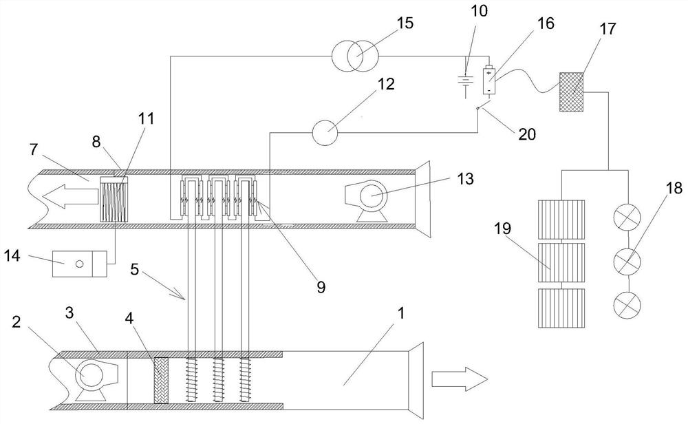
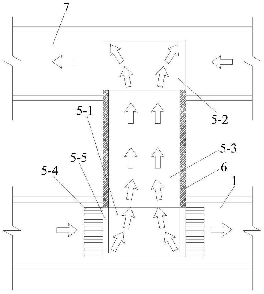
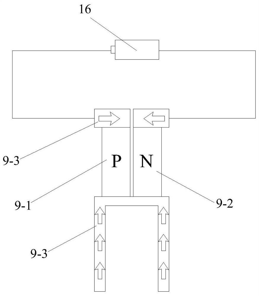
[0051] Such as Figure 1 to Figure 5 The comprehensive utilization system for waste heat recovery of the return air shaft in the cold mining area shown includes the return air shaft 1, the air intake shaft 7, the waste heat recovery preheating mechanism connected between the return air shaft 1 and the air intake shaft 7, and the air intake shaft The thermoelectric conversion system matched with the waste heat recovery and preheating mechanism in 7, the thermoelectric conversion system is connected with the storage battery 16 and the external power supply 10 through a single-pole double-throw switch 20, the output terminal of the thermoelectric conversion system and the storage battery 16 A voltage stabilizer 15 is connected, the return air shaft 1 is provided with a return air fan 2, the air intake shaft 7 is provided with an air intake fan 13 and an electric auxiliary heater 11, and the thermoelectric conversion system is located in the electric auxiliary heating Between devi...


PUM


Abstract

The invention discloses a waste heat recovery and comprehensive utilization system and method for an air return shaft in a cold mining area. The waste heat recovery and comprehensive utilization system comprises a waste heat recovery preheating mechanism and a semiconductor thermoelectric conversion mechanism. The waste heat recovery and comprehensive utilization method comprises the following steps that step 1, a return air filter screen is mounted; step 2, mine return air in the return air shaft is filtered; step 3, mine return air waste heat is recycled and inlet air is pretreated; step 4, whether the air flow temperature in an air inlet shaft is larger than the set lowest temperature or not is judged; step 5, the semiconductor thermoelectric conversion mechanism charges a storage battery; step 6, the semiconductor thermoelectric conversion mechanism heats the inlet air; step 7, whether the air flow temperature in the air inlet shaft is larger than the set lowest temperature or not is judged again; and step 8, an electric auxiliary heater heats the inlet air. According to the waste heat recovery and comprehensive utilization system and method for the air return shaft in the cold mining area, return air waste heat can be recycled; and meanwhile, inlet air preheating and thermoelectric power generation can be carried out through the recycled waste heat, energy comprehensive utilization of power generation is achieved while inlet air is heated, the energy utilization rate is increased, the best use of materials is achieved, and inherent assets of mine construction are saved.

Description

technical field [0001] The invention belongs to the technical field of mine waste heat recycling and energy saving, and in particular relates to a comprehensive utilization system and method for waste heat recovery of return air wells in cold mining areas. Background technique [0002] Low temperature is a major factor restricting mine mining. my country's "Safety Regulations for Metal and Nonmetal Mine" (GB 16423-2020) clearly states that the air temperature in the air inlet shaft should not be lower than 2°C; when it is lower than 2°C, there should be air Heating facilities, and open flames should not be used to directly heat the air entering the mine. There are many existing cold mining areas in my country. On the one hand, in the northern part of China, due to the high latitude, the ambient temperature in winter is low, and the temperature of the air inlet of the mine is generally lower than 2°C without preheating; on the other hand, the demand for resources in recent yea...

Claims


Application Information

Patent Timeline
Patent Type & Authority Applications(China)
IPC IPC(8): E21F1/00H02N11/00H02J7/32F28D15/02
CPCE21F1/006H02N11/002H02J7/32F28D15/025
Inventor 徐宇李孜军王君健陈寅贾敏涛李蓉蓉王巧莉章梦胜张修智
Owner CENT SOUTH UNIV
Learn More