
Patsnap Eureka
For R&D, Patsnap Eureka makes reading and utilizing patents & technical documents easy.
Patsnap Eureka AIR
Designed for self-driven R&D workflows. Generate viable solutions, solve complex R&D challenges, empower your innovation with AI.

Patsnap Eureka Materials
Designed for material experts only. Revolutionize your material R&D, from search, analyze, to developing new materials.

TechResearch
Generate reliable direction feasibility study reports for your R&D in just a few steps.

TechSeek
Discover and master advanced knowledge NOW. Basics, ideas, possibilities, all at once.

TechMind
As an expert in R&D Theories, TechMind can generates customized viable solutions instantly.

TechRisk
Analyze your overall solution with one click, know your potential R&D risks in advance.

TechMonitor
Get weekly tech updates, stay abreast of the latest tech innovations and key insights.
Rotating mandrel device for limited motion mandrel mill
A technology of rotating device and restraining mandrel, applied in metal rolling, metal rolling, metal processing equipment and other directions, can solve the problems of difficulty in stripping the restraining mandrel in a continuous pipe rolling mill, and achieve longer length and extended use. Longevity, effect of reducing thermal load
- Summary
- Abstract
- Description
- Claims
- Application Information
AI Technical Summary
Problems solved by technology
Method used
Image

Examples
Embodiment Construction
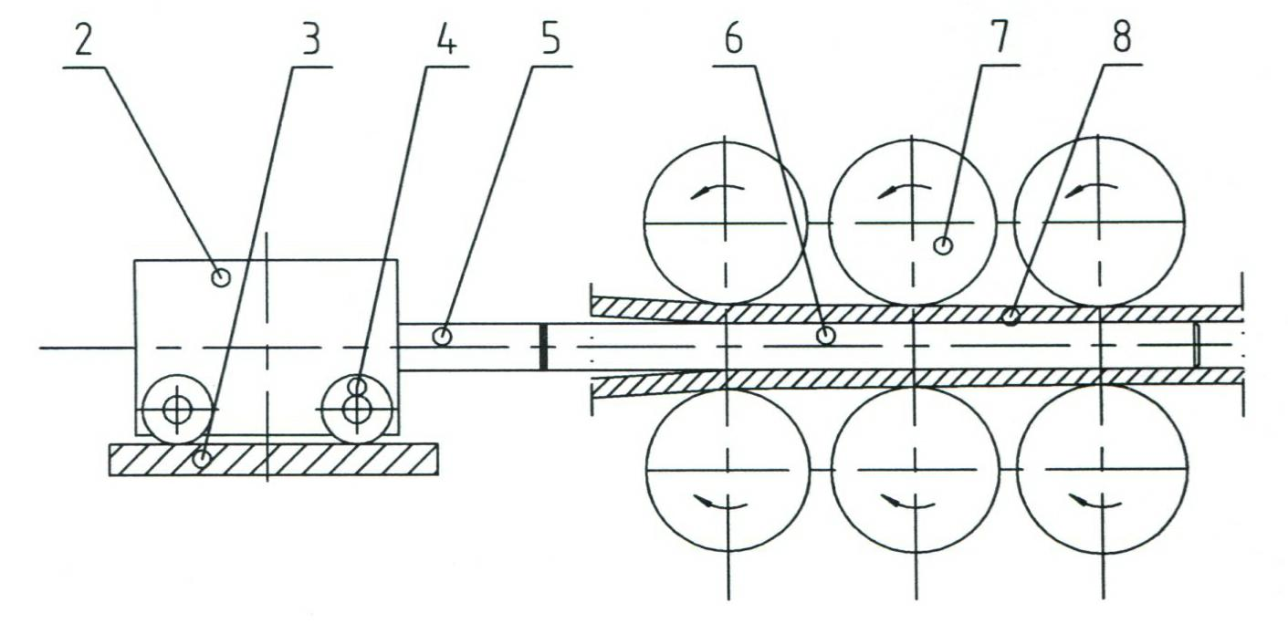
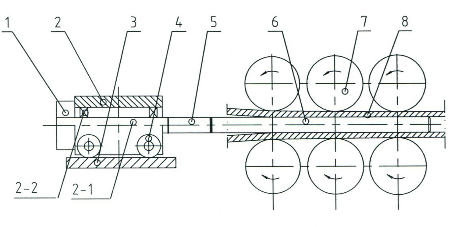
[0013] Such as image 3 As shown, a rotating mandrel device for a mandrel-limiting continuous rolling mill, including: a mandrel-limiting trolley 2, a support rod 5 connected to the mandrel-limiting trolley 2 through a flange, and a support rod 5 Threaded connection with the mandrel 6; the main shaft 2-1 of the mandrel stop trolley 2 is connected with the active rotation device 1 through a flange, and the main shaft 2-1 is installed between the shell of the mandrel stop trolley 2 There are bearings 2-2.
[0014] The active rotating device 1 is a hydraulic motor, or a motor-belt, motor-sprocket drive, or a servo motor direct drive.
[0015] Working process of the present invention:
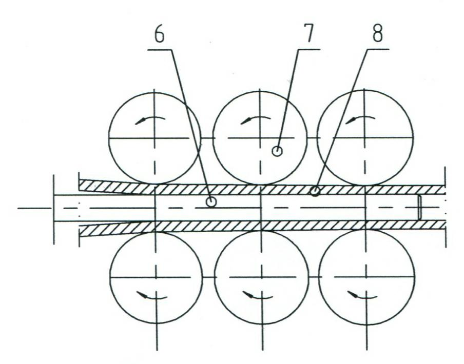
[0016] The wheel 4 of the mandrel stop trolley 2 runs along the guide rail 3 under the constraint of the stop cylinder. Under the rotation of the roll 7, the pipe 8 enters the rolling section for longitudinal rolling, and the mandrel 6 moves forward or backward according to the process requiremen...
PUM
 Abstract
Description
Claims
Application Information
 - R&D Engineer
- R&D Manager
- IP Professional
- Industry Leading Data Capabilities
- Powerful AI technology
- Patent DNA Extraction
Browse by: Latest US Patents, China's latest patents, Technical Efficacy Thesaurus, Application Domain, Technology Topic, Popular Technical Reports.
© 2024 PatSnap. All rights reserved.Legal|Privacy policy|Modern Slavery Act Transparency Statement|Sitemap|About US| Contact US: help@patsnap.com