A quick-release slip drilling template

A technology for unloading slips and drilling molds, which is applied to the drilling molds used for workpieces, etc., and can solve the problems of not being suitable for quick production changes, labor and time-consuming, and high manufacturing costs.

Inactive Publication Date: 2011-12-21
TIANRUN IND TECH CO LTD
View PDF6 Cites 2 Cited by
  • Summary
  • Abstract
  • Description
  • Claims
  • Application Information

AI Technical Summary

Problems solved by technology

However, due to the variety of processed crankshafts, in order to adapt to the clamping of different main journals, the slips must be replaced. Usually, the slips are pushed out of the mechanism with a tilting pin. This mechanism needs to drill a guide hole

Method used


Image

  • A quick-release slip drilling template
  • A quick-release slip drilling template
  • A quick-release slip drilling template

Examples


Embodiment Construction

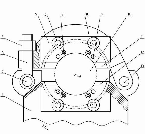
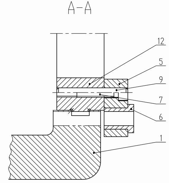
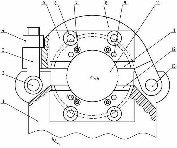
[0010] From figure 1 , figure 2 It can be seen from the figure that a quick-release slip drilling template includes a clamp body 1, a lower lining tile 12, a gland 8, an upper lining tile 11, a lining column 10, a drilling template 5, a drill sleeve 6, etc. Concrete 1 and the gland 8 are provided with grooves, and the lower lining tile 12 and the upper lining tile 11 are respectively provided with bosses in the circumferential direction, and the lower lining tile 12 and the upper lining tile 11 are tightly fitted in the clamp body 1 and the gland respectively. 8, one end of the gland 8 is connected to one side of the clamp body 1 through a hinge pin 13, the other side of the clamp body 1 is connected to a flat head bolt 3 through a pin shaft 2, and the other end of the gland 8 is provided with a U-shaped Mouth, the U-shaped mouth penetrates the flat head bolt 3, connects with the compression nut 4, and clamps the lining column 10 between the lower lining tile 12 and the uppe...


PUM


Abstract

The invention relates to a drilling jig for drilling on a quick-release slip. The drilling jig comprises a clamp body, a lower lining tile, a gland, an upper lining tile, a lining column, a drilling jig plate and a drill bushing, wherein grooves are arranged on the clamp body and the gland, bosses are correspondingly arranged on the lower lining tile and the upper lining tile in the circumferential direction, the lower lining tile and the upper lining tile are closely fitted and embedded in the grooves of the clamp body and the gland respectively, one end of the gland is connected with one side of the clamp body through a hinge pin, a U-shaped port is arranged at the other end of the gland, a flat head bolt and a compression nut are used for connection, the lining column is tightly clamped between the lower lining tile and the upper lining tile, screw holes and pin holes are arranged on the side surfaces of the upper lining tile and the lower lining tile, a countersunk hole and a pin hole are correspondingly arranged on the drilling jig plate and fixed with the upper lining tile and the lower lining tile respectively through a screw and a positioning pin, and a drill bushing is fixedly mounted on the drilling jig plate. The drilling jig is reasonable in structure, simple for manufacturing and convenient for mounting and clamping, and can realize drilling of circular holes on the clamp body and the inner edge of the gland; furthermore, the positions of the drilled holes are accurate, and the drilling jig is suitable for the quick-release slips and can be applied to quick changeovers.

Description

technical field [0001] The invention relates to a clamp removal drilling device, in particular to a quick-release slip drilling mold. Background technique [0002] We know that the clamps used for turning or grinding crankshaft pins, in order to improve the wear resistance of the clamped crankshaft main journal, slips are inlaid on the corresponding parts of the clamp body and the gland. When installing, just press the boss of the slip into its groove. However, due to the variety of processed crankshafts, in order to adapt to the clamping of different main journals, the slips must be replaced. Usually, the slips are pushed out of the mechanism with a tilting pin. This mechanism needs to drill a guide hole in the front of the clamp body. Proper machine tool processing requires the overall installation and alignment of the clamp body, which is labor-intensive and time-consuming, not suitable for quick production changes, and the manufacturing cost is also high. Contents of ...

Claims


Application Information

Patent Timeline
IPC IPC(8): B23B47/28
Inventor 孙海涛宋文友张良谭金成揭晓东武刚
Owner TIANRUN IND TECH CO LTD
Why Eureka
Try Eureka