A wrist of a two-degree-of-freedom industrial robot

A technology of industrial robots and degrees of freedom, applied in the direction of manipulators, manufacturing tools, joints, etc., can solve the problems of unguaranteed accuracy, low flexibility, difficult to control accuracy, etc., achieve simple structure, improve power transmission accuracy, and rotate wide range of effects

Inactive Publication Date: 2011-12-21
GSK CNC EQUIP
View PDF10 Cites 19 Cited by
  • Summary
  • Abstract
  • Description
  • Claims
  • Application Information

AI Technical Summary

Problems solved by technology

The main feature of the three-degree-of-freedom offset wrist is that the end of the wrist is offset on one side of the midline of the forearm. Not on a line, so the kinematic inverse solution of the three-degree-of-freedom offset wrist is more complicated to solve, and the dynamic parameters are also strongly coupled
The advantage of the three-degree-of-freedom converging wrist is that it is convenient for robot modeling and kinematics analysis, but due to the limitation of the joint structure, the fifth degree of freedom in the plane Y 3 o 3 Z 3 inside (see figure 1 )β≤200°, so its flexibility is lower than that of the three-degree-of-freedom offset wrist; at the same time, the structure of the spherical intersection wrist is also more complicated, which requires high machining accuracy and assembly accuracy of the parts, otherwise it is difficult to guarantee the rotation The axes of the angles α, β, and γ meet at a point
When the motor is placed at the rear end of the forearm, the torque of the motor is transmitted to the wrist at the front end of the forearm by means of the hollow shaft. Very high, otherwise the accuracy will not be guaranteed due to long-distance transmission
However, when the motors are vertically placed side by side in the cavity of the forearm, the power is transmitted to the wrist through gears and belt transmission. This structure is suitable for flat and long motors. After many passes, the structure of the wrist is complicated, and its precision is difficult to control

Method used


Image

  • A wrist of a two-degree-of-freedom industrial robot
  • A wrist of a two-degree-of-freedom industrial robot
  • A wrist of a two-degree-of-freedom industrial robot

Examples


Embodiment

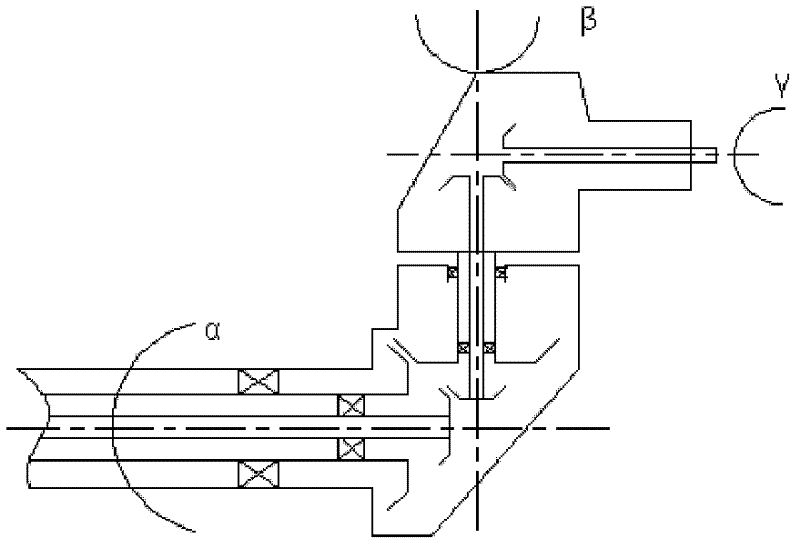
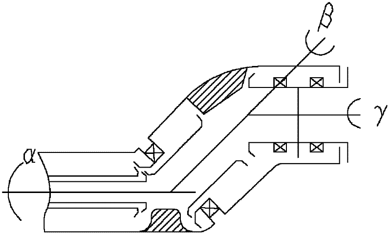
[0034] The wrist of a two-degree-of-freedom industrial robot in this embodiment has a structure such as Figure 7 or Figure 8 As shown, it includes a rotation drive mechanism and a pitch drive mechanism. The rotation drive mechanism includes a power input shaft 1, a bevel gear set 2 and a rotation gear shaft 3. One end of the power input shaft 1 and one end of the rotation gear shaft 3 are connected by the bevel gear set 2 , The other end of the power input shaft 1 is externally connected with a self-rotating power source, the other end of the rotation gear shaft 3 is connected with the wrist end effector, the power input shaft 1 and the rotation gear shaft 3 are arranged perpendicularly, and the power input shaft 1 is arranged in the axial direction of the wrist base 4 The pitch drive mechanism includes a pitch gear shaft 5, one end of the pitch gear shaft 5 is externally connected with a pitch power source, the other end of the pitch gear shaft 5 is connected to the wrist bas...


PUM


Abstract

The invention discloses a wrist of a two-degree-of-freedom industrial robot, which includes an autorotation drive mechanism and a pitch drive mechanism. The autorotation drive mechanism includes a power input shaft, a bevel gear set, and an autorotation gear shaft. The other end of the power input shaft is connected to the rotation power source, the other end of the rotation gear shaft is connected to the wrist end effector, the power input shaft and the rotation gear shaft are vertically arranged, and the power input shaft is set in the axis direction of the wrist base; The drive mechanism includes a pitch gear shaft. One end of the pitch gear shaft is externally connected to a pitch power source. The other end of the pitch gear shaft is connected to the wrist base. The pitch gear shaft is arranged in the axial direction of the wrist base. The wrist of this industrial robot sets the rotation drive mechanism and the pitch drive mechanism separately to realize the independent movement of the two degrees of freedom. The rotation range of each degree of freedom is large and does not interfere with each other. At the same time, its structure is simple, which is conducive to the balance of the forearm and the stable operation of the robot. sex.

Description

Technical field [0001] The invention relates to the technical field of industrial robots, in particular to a wrist of an industrial robot with two degrees of freedom. Background technique [0002] The modern robot wrist is also called the robot's posture mechanism. Since the wrist rod has a rotating motion around itself (ie the sixth joint), if the wrist rod can take any position in space, then the associated end effector will be It can take any posture in space, that is, it can achieve complete flexibility, because the posture of the rod can be determined by two directions, such as figure 1 As shown, in the figure 32 is the big arm of the robot, 33 is the forearm, 34 is the wrist end rod, and the end of the wrist end rod is connected to the end effector. In the figure, the illustrated posture of the wrist rod can be seen as 3 The original position of the direction first goes around Z 3 In plane X 3 O 3 Y 3 Rotate inside by α angle, then in Y 3 With Z 3 Vertical plane Y 3 O 3 Z 3...

Claims


Application Information

Patent Timeline
Patent Type & Authority Applications(China)
IPC IPC(8): B25J17/02
Inventor 陈其忠张铁张爱民邹焱飚
Owner GSK CNC EQUIP
Why Eureka
Try Eureka