A workpiece transfer device for machining

A transfer device and machining technology, applied in manual conveying devices, transportation and packaging, etc., can solve the problem of high transfer cost of machined workpieces, reduce the cost of mechanical equipment and power costs, avoid collisions, and reduce friction.

Inactive Publication Date: 2011-12-21
CHENGDU KESHENG PETROLEUM TECH +1
View PDF6 Cites 2 Cited by
  • Summary
  • Abstract
  • Description
  • Claims
  • Application Information

AI Technical Summary

Problems solved by technology

[0003] The object of the present invention is to provide a workpiece transfer device for machining, which overcomes the problem of high transfer cost of machining workpieces

Method used


Image

  • A workpiece transfer device for machining
  • A workpiece transfer device for machining

Examples


Embodiment

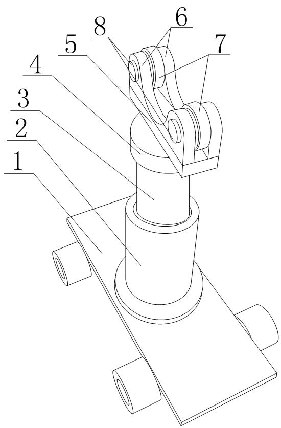
[0018] Such as figure 1 As shown, a workpiece transfer device for mechanical processing of the present invention includes a transfer trolley 1, the transfer trolley 1 is composed of a vehicle body and wheels, a sleeve 2 is arranged on the vehicle body, and the sleeve 2 is sleeved with the sleeve 2 Matching sleeve column 3, the length and diameter of sleeve column 3 match the internal length and inner diameter of sleeve 2, and a limit structure 4 is arranged on the top of sleeve column 3, and the diameter of limit structure 4 is between that of sleeve 2. Between the inner diameter and the outer diameter, a workpiece storage device is installed on the limit structure 4. The workpiece storage device includes a horizontal plate 5, and the horizontal plate 5 is installed at the top center of the limit structure 4. Two The vertical plates 6 are parallel to each other, the middle position of the vertical plates 6 is partially recessed downward to form an arc-shaped groove, and two ro...


PUM


Abstract

The invention discloses a workpiece transfer device for mechanical processing, comprising a transfer trolley (1), on which a sleeve (2) is fixedly installed, on the sleeve (2) The inner sleeve is provided with a sleeve column (3), and a workpiece storage device is arranged on the top of the sleeve column (3). In the present invention, by placing the workpiece in the workpiece storage device and transferring the workpiece to different locations through the transfer trolley, the cost of mechanical equipment and power is reduced, and resources are allocated and utilized reasonably; by setting two rollers on the workpiece storage device , can reduce the friction between the workpiece and the workpiece storage device, and effectively avoid the damage of the workpiece; the limit structure set on the top of the column can not only effectively limit the shaking, deviation, or even overturning of the column, but also can part of the workpiece The gravity is transmitted to the sleeve, which reduces the pressure of the sleeve column on the transfer trolley and reduces the pressure on the transfer trolley.

Description

technical field [0001] The invention relates to a transportation tool, in particular to a workpiece transfer device for mechanical processing. Background technique [0002] Machining is a process of changing the shape or performance of workpieces with processing machinery. According to the temperature state of the processed workpiece, it is divided into cold processing and hot processing: generally processing at room temperature, and does not cause chemical or physical phase changes of the workpiece, it is called cold processing; generally processing at a state higher or lower than normal temperature will be The chemical or phase change caused by the workpiece is called thermal processing. Cold processing can be divided into cutting processing and pressure processing according to the difference in processing methods; thermal processing commonly includes heat treatment, forging, casting and welding. Machining includes: filament power winding, laser cutting, heavy machining,...

Claims


Application Information

Patent Timeline
Patent Type & Authority Applications(China)
IPC IPC(8): B65G7/02
Inventor 贺昶明
Owner CHENGDU KESHENG PETROLEUM TECH
Why Eureka
Try Eureka