A multi-purpose electric plug

An electric latch, multi-purpose technology, applied in the field of locks, can solve the problems of outdated design and difficult to keep up with the rhythm of the times, and achieve the effect of strong versatility, simple structure and easy maintenance.

Inactive Publication Date: 2011-12-21
李万红
View PDF5 Cites 7 Cited by
  • Summary
  • Abstract
  • Description
  • Claims
  • Application Information

AI Technical Summary

Problems solved by technology

[0002] In the traditional sense, "bolt" is a very common lock in people's life. It can be found in daily cabinets, cabinets, doors, and w

Method used


Image

  • A multi-purpose electric plug
  • A multi-purpose electric plug
  • A multi-purpose electric plug

Examples


Example Embodiment

[0039] Example 1: Manual application.

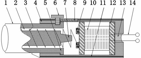
[0040] Such as figure 1 As shown, there is almost no big difference between the appearance of the multi-purpose electric plug and the traditional plug. Therefore, the multi-purpose electric plug of the present invention can be used for the position where the traditional plug is originally used. It is only used when the power is disconnected. The application of multi-purpose electric plug is only. The installation method of the multi-purpose electric plug is consistent with the installation method of the traditional plug, which is omitted. But it is slightly different from traditional bolts in specific use. Since the multi-purpose electric plug is disconnected from the power supply, the deadbolt spring (3) in the dual-purpose plug always acts on the deadbolt (1), and the deadbolt (1) is in the pin position (the bolt is extended ), then you only need to move the manual handle ( 6 ) to make the lock tongue ( 1 ) retreat or push the manua...

Example Embodiment

[0041] Example 2: Electric application.

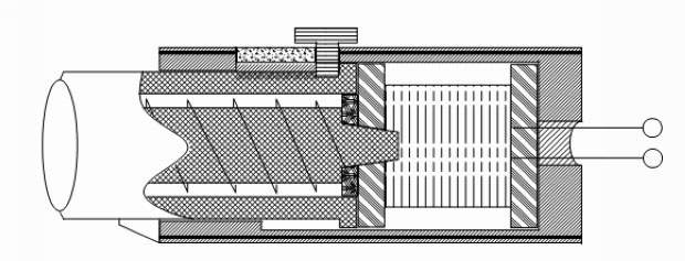
[0042] like figure 2 As shown, it is a structural schematic diagram of an automatic vending machine for opening the door to pick up goods. The electric latch (3) in the figure is programmed and controlled by the PLC control system (12). When the operating elements of the automatic vending machine meet the conditions, the PLC control system (12) The unpacking procedure will be started, and the electric latch (3) will execute the release command.

[0043] Its action mechanism is: when the electric plug (3) receives the PLC control system (12) release signal (that is, the power is turned on), the coil (10) on the coil holder (12) generates a magnetic field due to the power being turned on, and the electromagnet The core ( 9 ) is magnetized, and the magnetic force generated by the electromagnet core ( 9 ) first attracts the lengthened tail ( 7 ) at the end of the lock tongue ( 1 ), and the lock tongue ( 1 ) is instantly attracted by the ...


PUM


Abstract

The invention relates to the field of locks, in particular to a multipurpose electric bolt which has a simple structure and a wide application range. The multipurpose electric bolt consists of a lock tongue (1), a locking spring cavity (2), a lock tongue spring (3), an outer shell (4), a limiting stopper (5), a manual handle (6), a lengthening tail (7), a T-shaped sliding chute (8), magnetized iron cores (9), a coil (10), a closing wire (11), a coil frame (12), a wire hole (13), a power line (14), an installation seat (15) and an installation screw hole (16). The multipurpose electric bolt is actually a deformation relay which is obtained after the structure of the solenoid valve is lengthened and is subjected to variation processing. In the electrification state, a magnetic field produced by the coil magnetizes the iron core; when magnetic force produced by magnetizing the iron core overcomes the elastic force of the lock tongue spring, the lengthening tail (7) of the lock tongue (1) is attracted first, and when the body of the lock tongue (1) is completely attracted completely, the multipurpose electric bolt is unlocked; and after the power supply is disconnected, the magnetic field disappears, the lock tongue (1) is reset by the lock tongue spring (3), and the bolt is locked again. The multipurpose electric bolt has a simple structure, so the manufacturing cost is relatively low; therefore, the multipurpose electric bolt can be widely applied to the fields of automatic control and daily necessities.

Description

technical field [0001] The invention relates to the field of locks, in particular to a multipurpose electric plug with simple structure. Background technique [0002] In the traditional sense, "bolt" is a very common lock in people's life. It can be found in daily cabinets, cabinets, doors, and windows, but most of them are "hundred-year-old brands" with outdated designs and the same appearance. It's hard to keep up with the times. Contents of the invention [0003] With the advancement of science and technology, automatic control technology has been developing rapidly, and the demand for electric components with similar "plug" functions is also increasing. Complicated and expensive, not to mention balanced and versatile. [0004] The present invention solves the above-mentioned deficiencies, and discloses a multi-purpose electric plug with novel design, trendy appearance, simple structure and low cost, which can be compatible with automatic control schemes and can inher...

Claims


Application Information

Patent Timeline
IPC IPC(8): E05B47/02E05B63/08
CPCE05B47/02E05B63/08E05B47/0002E05B47/026E05B63/18E05B65/02G07F17/12
Inventor 李万红
Owner 李万红
Why Eureka
Try Eureka