sprocket

A sprocket and chain technology, applied in the direction of belts/chains/gears, portable lifting devices, components with teeth, etc., can solve the problems of bad influence of chain transmission devices, difficult aging, serious aging, etc., to prevent Harmful effects, reduced localized aging, reduced shattering effects

Active Publication Date: 2011-12-21
TSUBAKIMOTO CHAIN CO
View PDF4 Cites 9 Cited by
  • Summary
  • Abstract
  • Description
  • Claims
  • Application Information

AI Technical Summary

Problems solved by technology

[0010] Therefore, the problem is that in the narrow area between U1 and G1 on the gasket 520, deformation along the torsion direction occurs repeatedly, local aging occurs, and when elastic materials such as rubber are used, cracking and the like also occur. These debris can have a severe adverse effect on the applied chain drive
[0011] Also, especially when the sprocket has an odd number of teeth, there is a problem, as Figure 10 As shown in (b), the areas U1, U2 pressed by the inner link plate and the areas G1, G2 pressed by the outer link plate will repeatedly appear in a state where the other side is not pressed at all every time the sprocket rotates once. , so in the width direction, in the extremely narrow area at the junction of adjacent areas, every time it rotates once, large deformations in the opposite direction will alternately occur, making the aging more serious, and it is very easy to cause breakage, etc. Phenomenon
[0012] In the washer of the aforementioned Patent Document 1, although the degree of aging caused by the alternating deformation in the twisting direction is alleviated after the grooves are provided, when the number of teeth of the sprocket is odd, due to the reverse direction caused by each rotation Aging caused by large deformation is difficult to alleviate

Method used


Image

  • sprocket
  • sprocket
  • sprocket

Examples


Embodiment 1

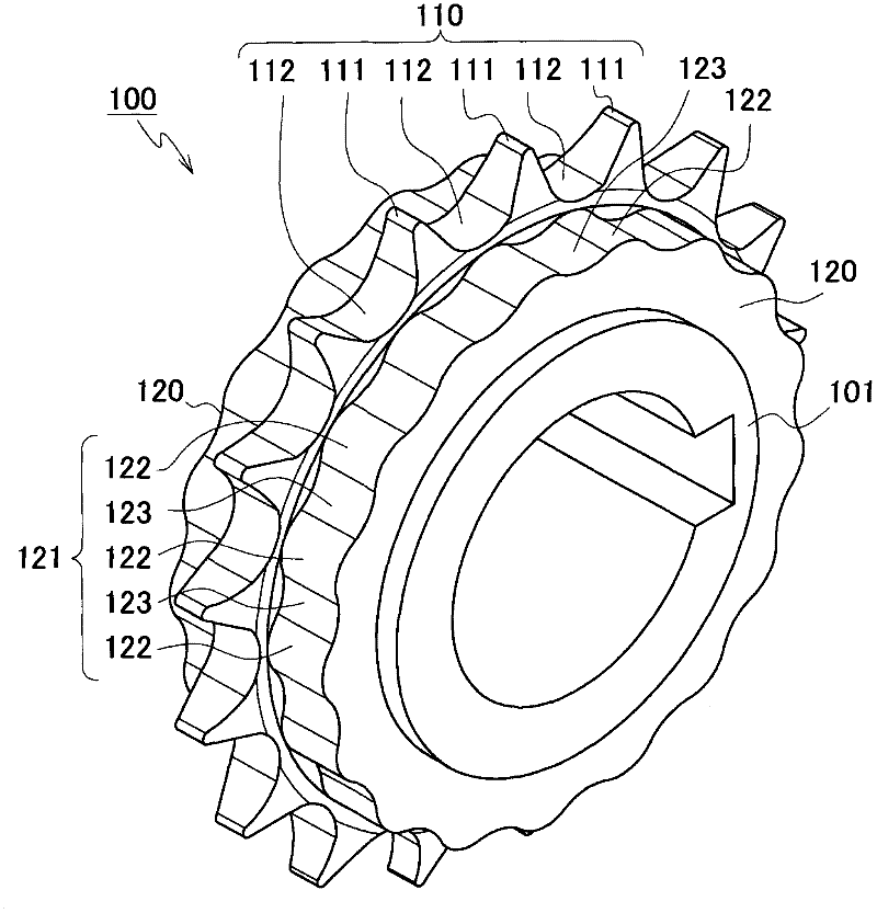
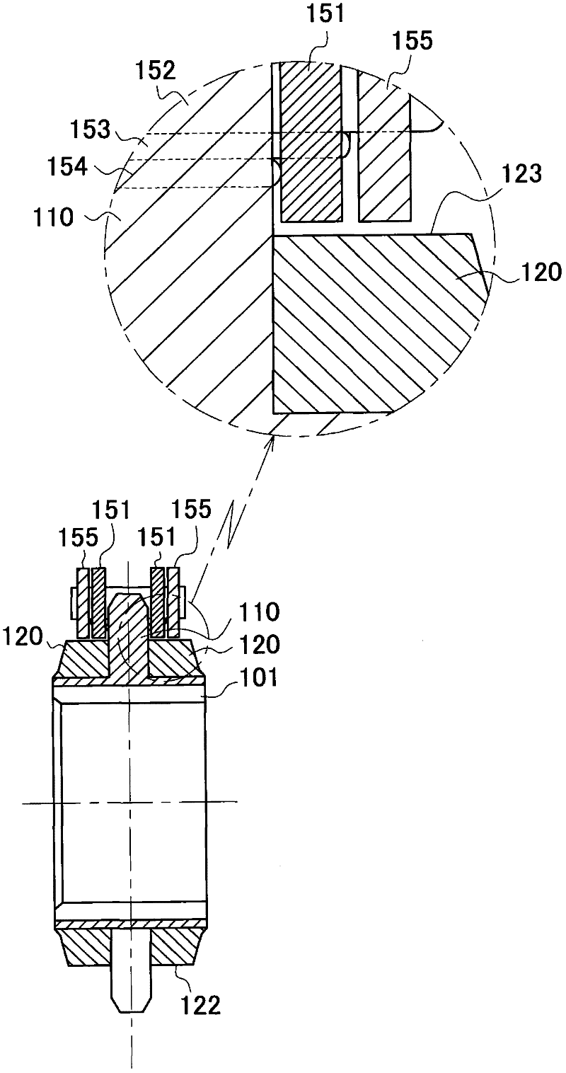
[0065] The sprocket 100 according to the first embodiment of the present invention, as Figure 1~3 As shown, a plurality of teeth 110 with tooth tips 111 and dedendums 112 are formed on the peripheral surface of the sprocket body 101, and outer peripheral surfaces 121 are provided on both sides of the sprocket body 101 to contact the chain plate of the chain. And a washer 120 made of elastic components.

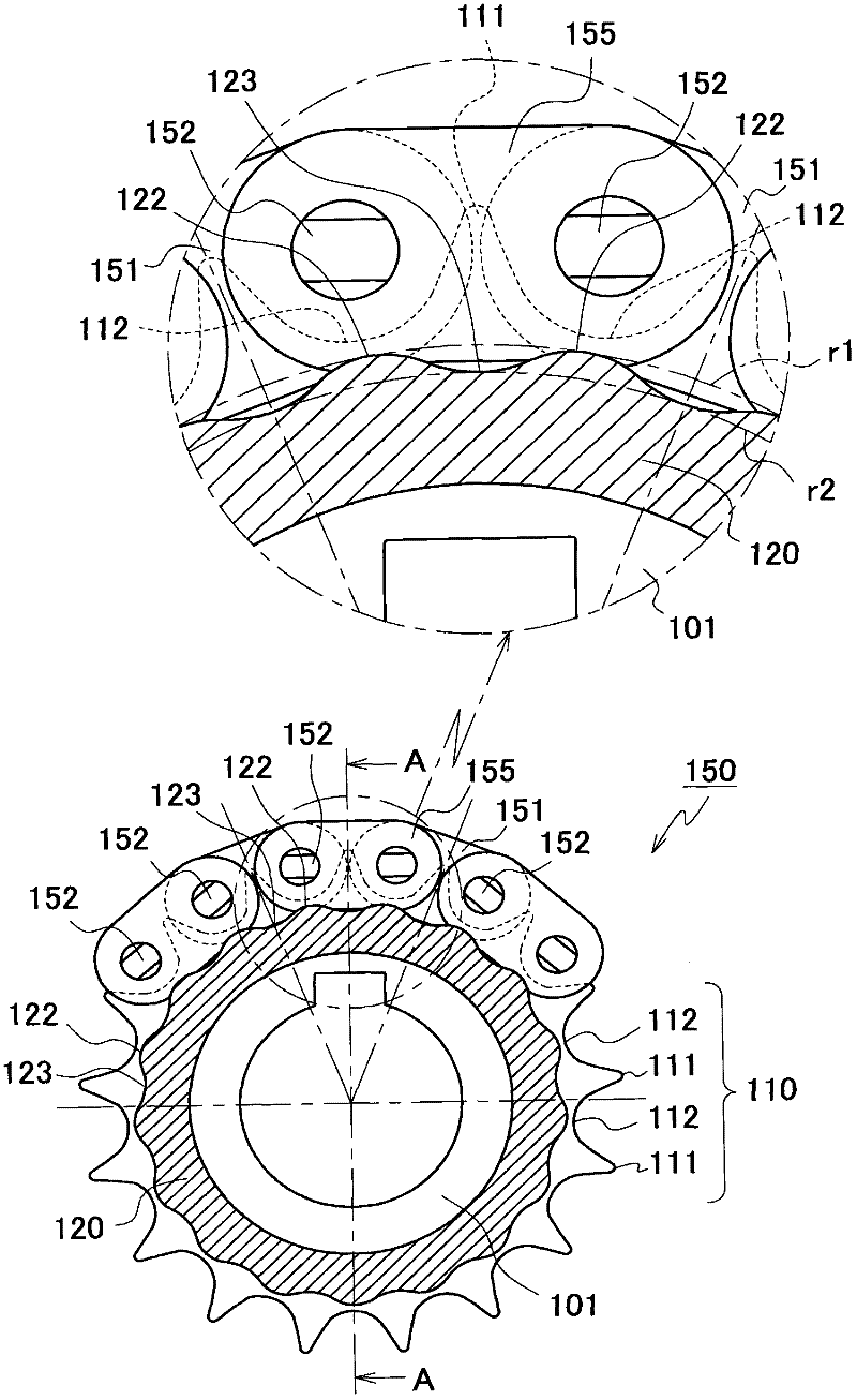
[0066] On the outer peripheral surface 121 of the washer 120 located on both sides, convex portions 122 and concave portions 123 as non-cylindrical portions are alternately provided along the circumferential direction, and the convex portions 122 are formed at positions corresponding to the dedendum 112. The portion 123 is formed at a position corresponding to the tooth tip 111 . In addition, the "corresponding position" in the circumferential direction referred to in this specification means a position having the same angle as that of the sprocket 100 in the circumferential...

Embodiment 2

[0072] Compared with the first embodiment, the sprocket 200 described in the second embodiment of the present invention is only different in the washer 220, while other structures are the same. Such as Figure 4 The washer 220 of the sprocket 200 according to the second embodiment shown has an inner link plate 151 similar to the conventional washer at a position corresponding to the inner link plate 151 of the chain 150 in the width direction of the outer peripheral surface 221. The central part along the longitudinal direction contacts and presses the cylindrical surface 221U.

[0073] At a position corresponding to the outer link plate 155 of the chain 150 in the width direction on the outer peripheral surface 221 of the washer 220, there are provided convex portions 222 and concave portions 223 alternately in the circumferential direction as in the first embodiment. . The convex portion 222 is formed at a position corresponding to the tooth tip 211 , and the concave porti...

Embodiment 3

[0077] The sprocket 300 according to the third embodiment of the present invention is as follows: Figure 6 As shown, compared with the first embodiment or the second embodiment, only the radii of the convex portion 322 and the concave portion 323 of the washer 320 are different, and other structures are the same. The washer 320 of the sprocket 300 according to the third embodiment is alternately provided with convex portions 322L, 322S with different maximum radii and concave portions 323L, 323M, 323S with different minimum radii in the circumferential direction.

[0078] Accordingly, the state of the elastic material being pressed by the chain varies with each tooth of the sprocket 300, so the impact and knocking sound caused by the contact at the time of meshing are different for each tooth, thereby suppressing the vibration due to periodicity. Occurrence of resonance caused by permanent noise and shock.

[0079] In addition, only one of the maximum radius of the convex po...


PUM


Abstract

The invention provides a sprocket (100), which has a washer (120) in contact with the chain plates (151), (155) of the chain (150); Part of the outer peripheral surface (121) has a non-cylindrical portion with a radius smaller than that of the rest of the outer peripheral surface portion. Reduce the impact and impact sound caused by the contact with the chain, at the same time, reduce the local aging of the gasket, prevent the occurrence of breakage, etc., thereby reducing the overall vibration, damage and friction loss of the chain transmission device, so as to improve durability sex.

Description

technical field [0001] The present invention relates to a sprocket, comprising: a plurality of teeth formed on the circumferential surface of the body to engage with pins, bushes or rollers of the chain, and formed on the side of the body, the outer circumferential surface and the chain of the chain Gaskets where the plates are in contact. Background technique [0002] Currently widely used chain transmissions are chain transmissions with chains mounted on at least two sprockets on the driving side and the driven side for power transmission. It is desired to reduce the noise level in various applications. [0003] In particular, when the chain and the sprocket start to mesh, the impact noise caused by the contact of the pins, bushes or rollers with the teeth of the sprocket is the main cause of the noise, and the reduction of this noise is a problem to be solved by the chain drive . In addition, in addition to shocks caused by pins, bushes, or rollers starting to mesh and ...

Claims


Application Information

Patent Timeline
Patent Type & Authority Applications(China)
IPC IPC(8): F16H55/30
CPCF16H55/30F16H2055/306
Inventor 早见淳志森薰近能雅彦榑松勇二
Owner TSUBAKIMOTO CHAIN CO
Why Eureka
Try Eureka