led rotary built-in power fluorescent lamp

A fluorescent lamp, rotating technology, applied in the field of fluorescent lamps, can solve problems such as broken wires, unstable connection between the power board and the lamp board, and single function

Inactive Publication Date: 2011-12-21
NINGBO TONGTAI ELECTRIC
View PDF5 Cites 23 Cited by
  • Summary
  • Abstract
  • Description
  • Claims
  • Application Information

AI Technical Summary

Problems solved by technology

[0003] However, LEDs currently on the market as fluorescent lamps with built-in power sources have two obvious technical defects. First, the LED power board and the lamp board are connected by wires. This structure will lead to unstable connection between the power board and the lamp board. It is easy to press the wire, the wire is broken, etc.,

Method used


Image

  • led rotary built-in power fluorescent lamp
  • led rotary built-in power fluorescent lamp
  • led rotary built-in power fluorescent lamp

Examples


Embodiment 1

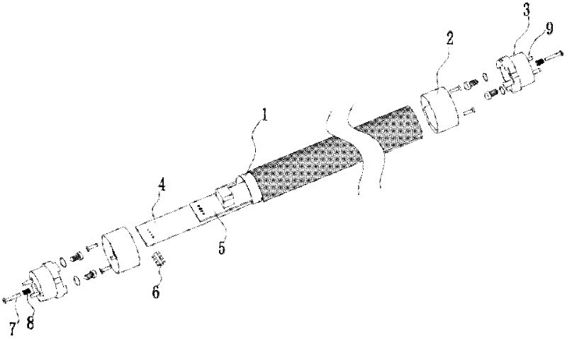
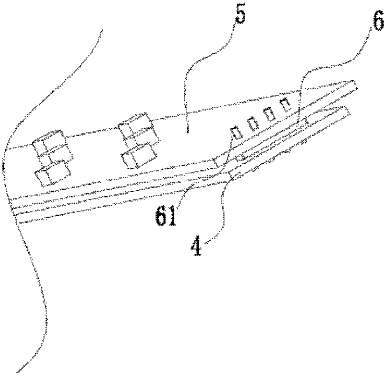
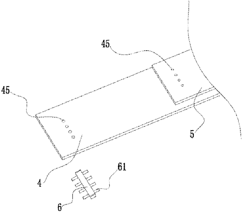
[0026] Such as figure 1 As shown, the LED rotary fluorescent lamp with built-in power supply provided by the present invention includes a lamp tube 1, a power supply assembly 5, a lamp panel assembly 4, two upper tube heads 3 and two lower tube heads 2, and each upper tube head 3 has a The lamp pins 9 are arranged symmetrically, the power supply assembly 5 and the lamp panel assembly 4 are located in the lamp tube 1, the power supply assembly 5 is located at the upper end of the lamp panel assembly 4, and the two lower tube heads 2 are respectively socketed at both ends of the lamp tube 1, each lower An upper pipe head 3 is nested outside the pipe head 2, such as figure 2 , image 3 As shown, between the power supply assembly 5 and the lamp panel assembly 4, a pin header 6 is installed to realize the electrical connection between the power supply assembly 5 and the lamp panel assembly 4. The pin header 6 is provided with four sets of pins 61 corresponding to conduction on bo...

Embodiment 2

[0032] Such as Figure 9 , Figure 10 , Figure 11 As shown, the general structure of the LED rotary fluorescent lamp with built-in power supply provided by this embodiment is consistent with that of Embodiment 1, but in order to further improve the safety of use, an insulating plate 14 is provided between the power supply assembly 5 and the lamp panel assembly 4, The lower end of the lamp panel assembly 4 is provided with a lampshade 10, and the lampshade 10 is fixed on the lamp tube 1; in order to improve the installation strength, a reinforcing rib 13 is provided on the partition 24 between the fixing hole 23 and the inner wall of the lower tube head 2; and In order to prolong the service life, the upper tube head 3 is provided with a tube head protective cover 12 that matches the lamp pin 9; a tube plug 11 is provided in the step mounting hole 33 of the upper tube head 3, and the tube plug 11 is located at the fastening position. outside of element 7.


PUM


Abstract

The invention discloses a LED rotary type built-in power source lamp, comprising a lamp tube (1), a power source component (5), a lamp panel component (4), two upper tube holders (3) and two lower tube holders (2); each upper tube holder (3) is provided with lamp pins (9), the power source component (5) and lamp panel component (4) are located in the lamp tube (1) ; two lower tube holders (2) are respectively sleeved on both ends of the lamp tube (1), the outer side of each lower tube holder (2) is nested with an upper tube holder (3) ; a pin header (6) is provided between the power source component (5) and the lamp panel component (4) for electrically connecting the power source component (5) with the lamp panel component (4), pins (61) are provided on the pin header (6) ; the power source component (5) and the lamp panel component (4) are all provided with jacks (45) welded with the pins (61) and all conducted with the corresponding electric connecting circuit; open ends of the two upper tube holders (3) are all provided with at least a position-adjusting boss (32) and a limit boss (31), the two lower tube holders (2) are all provided with clapboards (24); the joint part between the clapboards (24) and the inner walls of the lower tube holders (2) are provided with at least a position-adjusting stop (22) and limit stop (21). The invention has advantages of excellent connection stability and high electrical property, and can adjust the illuminating angles.

Description

technical field [0001] The invention relates to a fluorescent lamp, in particular to an LED rotary fluorescent lamp with a built-in power supply. Background technique [0002] As a sunrise industry, LED has been widely used in various light-emitting scenes, especially the recent development of LED technology, which has greatly improved the luminous efficiency of LED, so it is also favored by the lighting market. In indoor lighting, fluorescent lamps, or fluorescent lamps, are the most commonly used at present. Now there are also many kinds of fluorescent lamps made of LEDs as built-in power sources on the market. With the excellent performance of LEDs, they have become a new type of lamps to replace fluorescent lamps. [0003] However, LEDs currently on the market as fluorescent lamps with built-in power sources have two obvious technical defects. First, the LED power board and the lamp board are connected by wires. This structure will lead to unstable connection between th...

Claims


Application Information

Patent Timeline
IPC IPC(8): F21S9/00F21V23/06F21V17/10F21Y101/02
CPCF21V23/06F21Y2101/02F21K9/175F21S9/00F21Y2103/003F21K9/58F21V17/10F21K9/27F21K9/65F21Y2103/10F21Y2115/10
Inventor 仇富军
Owner NINGBO TONGTAI ELECTRIC
Why Eureka
Try Eureka