Combustion nozzle and coal gasification furnace
A combustion nozzle and gas-supporting technology, applied in the direction of burner, combustion method, combustion type, etc., can solve the problems of coolant outflow, influence on combustion, and uneven stress, so as to reduce possibility, improve life and reliability, The effect of optimizing the structure
- Summary
- Abstract
- Description
- Claims
- Application Information
AI Technical Summary
Problems solved by technology
Method used
Image
Examples
Embodiment 1
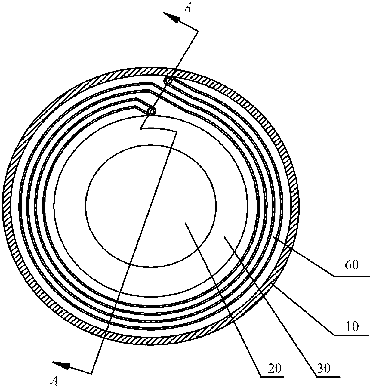
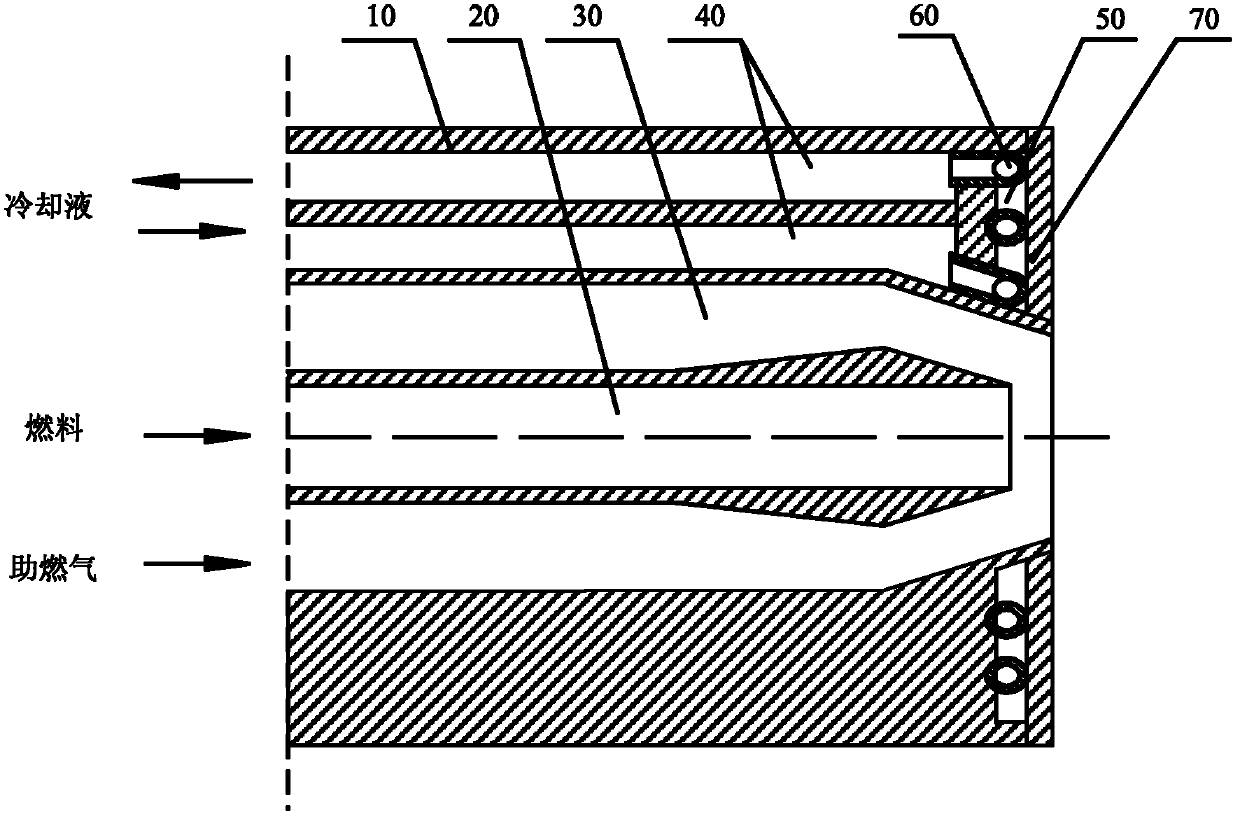
[0037] Figure 2A It is a schematic structural diagram of the combustion nozzle provided by Embodiment 1 of the present invention, Figure 2B for Figure 2A The schematic cross-sectional structure diagram along the A-A line, the combustion nozzle includes a nozzle housing 10, the nozzle housing 10 is provided with a fuel passage 20, a combustion gas passage 30 and a cooling passage 40, and the front end of the nozzle housing 10 is provided with a cooling chamber 50, Wherein, a helical pipeline 60 communicating with the cooling channel 40 is embedded in the cooling chamber 50 to form a helical cooling channel.
[0038] This embodiment is a preferred structure of the combustion nozzle. The fuel channel 20 is arranged along the longitudinal central axis of the nozzle housing 10, the gas-supporting channel 30 surrounds the outside of the fuel channel 20, and the cooling channel 40 can be arranged on the outside of the gas-supporting channel 30. . And, it is preferable that the ...
Embodiment 2
[0045] Figure 3A Schematic diagram of the structure of the combustion nozzle provided by Embodiment 2 of the present invention, Figure 3B for Figure 3A Schematic diagram of the cross-sectional structure along the B-B line, Figure 3C for Figure 3A Schematic diagram of the cross-sectional structure along line C-C. The difference between this embodiment and Embodiment 1 is that there are two cooling passages 40 provided in the casing 10, one of which communicates with the helical pipeline 60, and the other cooling passage 40 communicates with the other than the helical pipeline 60. The cooling cavity 50 communicates, such as Figure 3A , 3B and 3C are respectively provided with the inlet and outlet of two cooling passages 40 . Cooling passages 40 each including supply and return passages are provided on both sides of the housing 10 , respectively.
[0046] In this embodiment, the cooling cavity is separated into two spiral cooling channels by the spiral pipeline, and ...
Embodiment 3
[0049] Figure 4 The partial structural diagram of the combustion nozzle provided by Embodiment 3 of the present invention. This embodiment can be based on the above-mentioned technical solutions, and grooves 51 are formed on one or both end faces of the cooling chamber 50, usually formed on the nozzle shell On the front wall surface of the body 10 and the cover 70 , the shape of the groove 51 matches the shape of the helical pipeline, and the helical pipeline is buckled and fixed in the cooling cavity 50 .
[0050] The method of fixing the spiral pipeline provided in this embodiment can further reduce the point-shaped or linear connection between the spiral pipeline and the shell wall, increase the contact area between the spiral pipeline and the shell, and can not only improve heat conduction and cooling performance, and can avoid damage and fracture of the rigid joint due to uneven stress.
[0051] In addition, since the above-mentioned implementations use independent pipe...
PUM
 Abstract
Description
Claims
Application Information
 - R&D
- Intellectual Property
- Life Sciences
- Materials
- Tech Scout
- Unparalleled Data Quality
- Higher Quality Content
- 60% Fewer Hallucinations
Browse by: Latest US Patents, China's latest patents, Technical Efficacy Thesaurus, Application Domain, Technology Topic, Popular Technical Reports.
© 2025 PatSnap. All rights reserved.Legal|Privacy policy|Modern Slavery Act Transparency Statement|Sitemap|About US| Contact US: help@patsnap.com


