A solar concrete heat storage device for heat energy compensation of heat pumps

A heat storage device and concrete technology, applied in heat storage equipment, energy storage, indirect heat exchangers, etc., can solve the problems of relatively low heat storage density, high cost, and many parts

Inactive Publication Date: 2011-12-21
于奎明
View PDF4 Cites 5 Cited by
  • Summary
  • Abstract
  • Description
  • Claims
  • Application Information

AI Technical Summary

Problems solved by technology

Water heat storage uses the sensible heat characteristics of water temperature difference, but the relative heat storage density is small; phase chang

Method used


Image

  • A solar concrete heat storage device for heat energy compensation of heat pumps
  • A solar concrete heat storage device for heat energy compensation of heat pumps
  • A solar concrete heat storage device for heat energy compensation of heat pumps

Examples


Embodiment 1

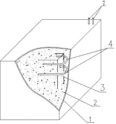
[0025] Example 1, such as figure 1 As shown, a solar energy concrete thermal storage device for heat pump thermal energy compensation includes concrete 2, the concrete 2 is provided with a steel frame 3, and the steel frame 3 is wound with D20 transmission material made of PE-RT material. The heat pipe 4 is provided with an insulating layer 1 made of asbestos material outside the concrete 2 .

[0026] Both ends of the heat transfer pipe 4 have pipe joints 7 respectively, and the pipe joints 7 are arranged outside the concrete 2 .

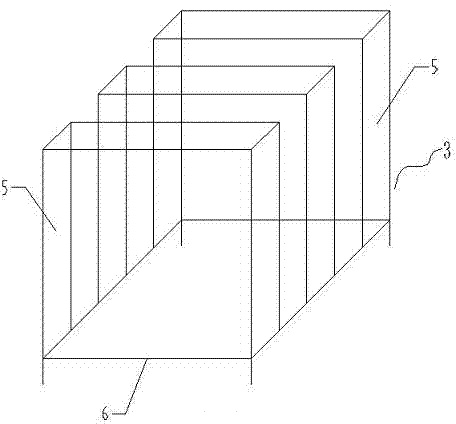
[0027] Such as figure 2 As shown, the reinforcement frame 3 includes three reinforcement cages 5 welded with M8 reinforcement and a reinforcement base 6 welded with M8 reinforcement, and the distance between the reinforcement cages 5 is 150 mm.

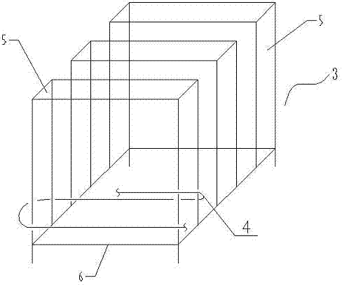
[0028] Such as image 3 As shown, the heat transfer tubes 4 are respectively wound on three reinforcement cages 5, with 8 turns evenly distributed on each reinforcement cage 5, and the heat transfer t...

Embodiment 2

[0035] Such as figure 1 As shown, a solar energy concrete thermal storage device for heat pump thermal energy compensation includes concrete 2, the concrete 2 is provided with a steel frame 3, and the steel frame 3 is wound with D20 transmission material made of PE-RT material. heat pipe4.

[0036] An insulating layer 1 made of asbestos material is provided outside the concrete 2 .

[0037] Both ends of the heat transfer pipe 4 have pipe joints 7 respectively, and the pipe joints 7 are arranged outside the concrete 2 .

[0038] Such as figure 2 As shown, the reinforcement frame 3 includes three reinforcement cages 5 welded with M8 reinforcement and a reinforcement base 6 welded with M8 reinforcement, and the distance between the reinforcement cages 5 is 200 mm.

[0039] Such as image 3 As shown, the heat transfer tubes 4 are respectively wound on three reinforcement cages 5, with 6 turns evenly distributed on each reinforcement cage 5, and the heat transfer tubes 4 are...


PUM

PropertyMeasurementUnit
Thicknessaaaaaaaaaa

Abstract

The invention discloses a solar energy concrete heat storage device for heat energy compensation of heat pumps, which comprises concrete, the concrete is provided with a steel frame, and the steel frame is wound with a heat transfer tube. The steel skeleton of the pipe is placed in the concrete formwork, the concrete is poured, and the pipe joint is reserved in a suitable position outside the concrete. Compared with the traditional hot water heat accumulator, the heat storage capacity of the present invention is greatly increased under the same volume. Concrete, as the heat storage matrix, is made by mixing cement, sand and gravel. These materials are readily available and relatively inexpensive.

Description

technical field [0001] The invention relates to a heat storage device, in particular to a solar concrete heat storage device used for heat energy compensation of a heat pump. Background technique [0002] my country is one of the countries with the most abundant solar energy resources in the world, with the total annual solar radiation exceeding 4200MJ / ㎡ accounting for 76% of the country's land area. Solar energy is a low-grade energy source with low calorific value. According to the principle of graded energy use, it can meet the needs of building and living energy. Therefore, vigorously promoting the application of solar energy in buildings is the most economical and reasonable choice to solve building energy consumption. [0003] Solar energy is a clean, cheap and inexhaustible source of energy, but the biggest obstacle to its utilization is its instability due to the influence of day and night, cloudy, rainy and snowy days. combined use of heat sources. When the solar...

Claims


Application Information

Patent Timeline
IPC IPC(8): F28D20/00
CPCY02E60/142Y02E70/30Y02E60/14
Inventor 于奎明
Owner 于奎明
Why Eureka
Try Eureka