Differential vertical micro-force measuring device and measuring method

A measuring device, differential technology, applied in the field of measurement, can solve problems such as micro force value not established, micro force calibration or measurement influence, temperature influence, etc., to achieve the effect of simple structure, accurate result, and elimination of lever deformation

Inactive Publication Date: 2011-12-21
HEFEI UNIV OF TECH
View PDF5 Cites 0 Cited by
  • Summary
  • Abstract
  • Description
  • Claims
  • Application Information

AI Technical Summary

Problems solved by technology

But the measurement system of tiny force value has not been established yet, so far, 10 -5 A traceable measurement method for micro- and nano-newton ultra-small force values ​​below Newton has not yet been established, so it is particularly important to develop an easy-to-use, low-cost micro-force value measuring and testing instrument to measure micro-force in various occasions
At present, micro-force measurement mainly includes piezoresistive, capacitive, piezoelectric, etc., piezoresistive force measurement is a force measurement device prepared by using the piezoresistive effect of piezoresistive materials, but this method is easily affected by temperature; The piezoelectric microcantilever type is easy to be interfered by the electromagnetic field, and the force measurement cost of the piezoelectric microcantilever is low, but the operation is inconvenient and the measuring range is small
[0003] At present, the flexible hinge mechanism has been widely used in the fields of precision measurement and calibration, but there is no good solution to the influence of the deformation of the flexible hinge, the position of the center of gravity of the lever, and the change of temperature on the accuracy of measurement and calibration. When calibrating or measuring, in order to obtain higher accuracy, the influence of the above aspects on the calibration or measurement of micro-force must be resolved. The influence of gravity and temperature may be far greater than the maximum range of micro-force calibration or measurement. For micro-force calibration or measure fatal effects

Method used


Image

  • Differential vertical micro-force measuring device and measuring method
  • Differential vertical micro-force measuring device and measuring method
  • Differential vertical micro-force measuring device and measuring method

Examples


Embodiment Construction

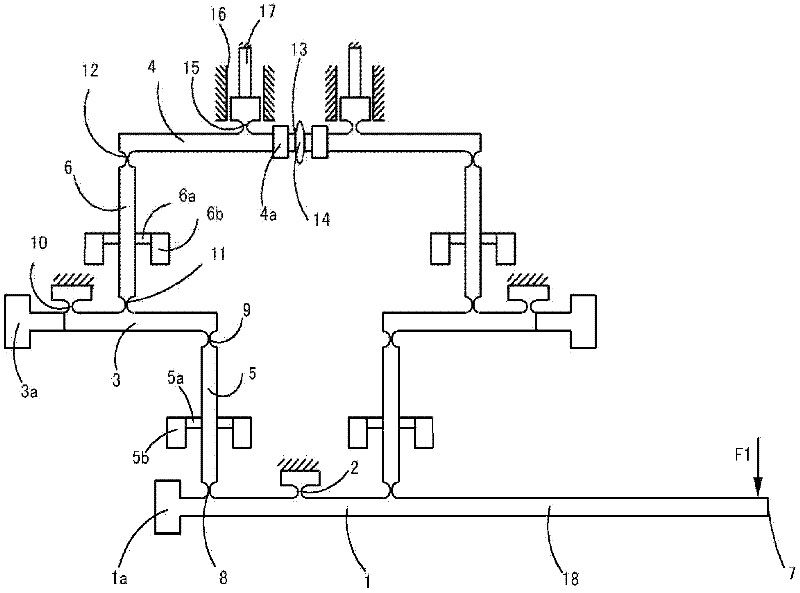
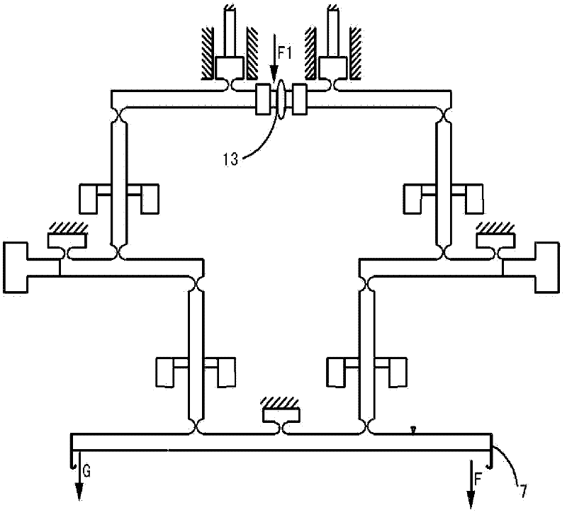
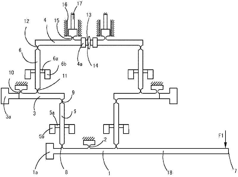
[0025] See figure 1 In this embodiment, a primary fulcrum 2 is set in the middle of the horizontally placed primary lever 1, with the primary fulcrum 2 as the center. In the same vertical plane, a pair of secondary levers 3 are symmetrically located at the primary fulcrum 2. The two sides of each side are connected to the first-level lever 1 through the first-level transition rod 5, and a pair of second-level levers 3 are also connected to the third-level lever 4 on each side through the second-level transition rod 6 respectively, in which:

[0026] figure 1 As shown, one end of the first-level lever 1 forms a free end 7 along the horizontal direction through the extension section 18. The free end 7 is the input end of the measured micro-force F1, and the non-free end of the first-level lever 1 passes through the first-level flexible The hinge 8 is connected to the bottom end of the primary transition rod 5; the top end of the primary transition rod 5 is connected to the inner end...


PUM


Abstract

The invention discloses a differential vertical micro force measuring device and a measuring method thereof. The device is characterized in that: a first-stage supporting point is arranged on the middle part of a horizontally-arranged first-stage lever, a pair of second-stage levers is symmetrically positioned on the two sides of the first-stage supporting point in the same vertical plane by taking the first-stage supporting point as a center, and each second-stage lever is connected with the first-stage lever through a first-stage transition rod on the side of the second-stage lever, and is connected with a third-stage lever through a second-stage transition rod on the side of the second-stage lever. By the device and the method, support can be provided for a force measuring system for amicro force value.

Description

Technical field [0001] The invention belongs to the field of measurement technology, and particularly relates to a micro-force measurement device. Background technique [0002] With the development of modern science and technology and the emergence of various new materials and new products, there are more and more occasions requiring micro-force measurement. However, the measurement system for the small force value has not been established. So far, 10 -5 The traceable measurement method of micro- and nano-newton-level ultra-small force values ​​below Newton has not been established. Therefore, it is particularly important to develop a convenient and low-cost micro-force measurement and test instrument to measure micro-forces in various occasions. At present, micro-force measurement mainly includes piezoresistive, capacitive, piezoelectric, etc. Piezoresistive force measurement is a force measurement device prepared by using the piezoresistive effect of piezoresistive materials, b...

Claims


Application Information

Patent Timeline
Patent Type & Authority Applications(China)
IPC IPC(8): G01L1/00
Inventor 王勇刘焕进杨科滑志龙尹鹏飞姜礼杰
Owner HEFEI UNIV OF TECH
Why Eureka
Try Eureka