Precise nanoindentation test device

A nano-indentation and testing device technology, applied in the direction of testing the hardness of materials, can solve the problems such as the inability to obtain the relationship between the mechanical and mechanical properties of the material and the evolution of the microstructure, the inability to test the mechanical parameters of the material, and the inability to study the law of load influence, etc. Simple, high electro-mechanical energy conversion rate, large stroke effect

Active Publication Date: 2013-02-06
长春因赛图精密仪器设备有限公司
View PDF7 Cites 0 Cited by
  • Summary
  • Abstract
  • Description
  • Claims
  • Application Information

AI Technical Summary

Problems solved by technology

[0004] There are many studies using indentation technology to determine the mechanical properties of materials. The indentation devices designed by foreign researchers, such as the indentation device designed by Bangert and Wagendristel, can be placed in the vacuum chamber of the scanning electron microscope, but they have not In-situ monitoring of the actual indentation process, in fact, they designed the instrument to overcome various constraints, such as positioning accuracy and detection of indentation marks under small loads (50μN–20mN)
Its main defect is the lack of load and displacement sensors, so the relationship between the mechanical and mechanical properties of the material and the evolution of the microstructure cannot be obtained; M.A.Wall of the Lawrence Livermore National Laboratory (LLNL) and the Lawrence Berkeley National Laboratory (LBNL) of the United States et al. first developed an in-situ nano-indentation device that is precisely driven by a gear motor and a piezoelectric element. Its main defect is that the mechanical parameters of the material cannot be tested due to the inability to detect the loading force, and the effect of the load on the deformation and damage of the material cannot be studied. The law of influence; the device of A.M.Minor etc. obtains the loading force by converting the relationship between the voltage applied to the piezoelectric element and its deformation, resulting in complex testing, too many offline operation links, and there are model errors and parameter errors in the conversion of loading force, which affect The credibility of the test results in terms of magnitude

Method used


Image

  • Precise nanoindentation test device
  • Precise nanoindentation test device
  • Precise nanoindentation test device

Examples


Embodiment Construction

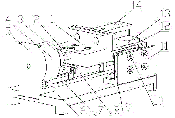
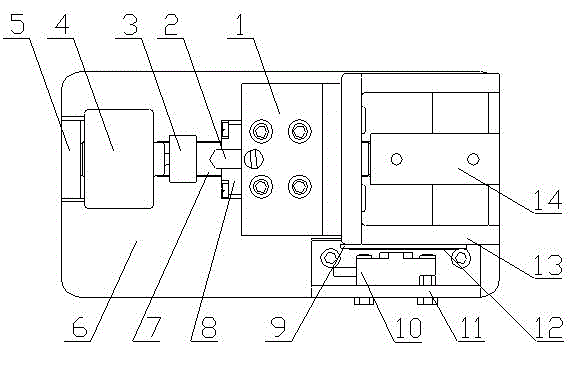
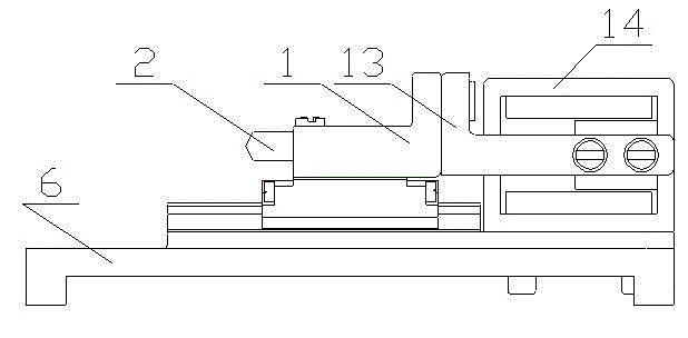
[0019] The detailed content of the present invention and its specific implementation will be further described below in conjunction with the accompanying drawings.

[0020] see Figure 1 to Figure 4 , the precision nano-indentation test device of the present invention includes a precision press-in drive unit, a load signal detection unit, and a displacement signal detection unit; the precision press-in drive unit includes a voice coil motor 14, a connector 13, a connecting plate 1, and a guide rail 7 and slider 8, the voice coil motor 14 and guide rail 7 are respectively fixed on the base 6, the connecting piece 13 is connected with the voice coil motor 14, the connecting piece 13 is connected with the connecting plate 1 through bolts, and the connecting plate 1 is connected on On the slider 8, the slider 8 is slidingly connected with the guide rail 7; the connecting plate 1 is driven by the voice coil motor 14, thereby realizing the linear movement of the slider 8 on the guid...


PUM


Abstract

The invention relates to a precise nanoindentation test device and belongs to the field of precise scientific instruments. The precise nanoindentation test device mainly comprises a precise press-in driving unit, a load signal and displacement signal detection unit and an objective table, wherein the precise press-in driving unit consists of a voice coil motor, a connecting piece, a guide rail and a sliding block; the voice coil motor and the guide rail are arranged on a pedestal; a precise mechanical sensor for detecting pressure of a diamond pressing head pressed into a material is arrangedon the pedestal through a side plate I; a precise displacement sensor for detecting diamond pressing head press-in depth is arranged on the pedestal through a side plate II; the objective table is arranged on the precise mechanical sensor; the diamond pressing head is arranged on the connecting plate; and the connecting plate is assembled on the sliding block through bolts. The precise nanoindentation test device has the advantages of simple structure, convenience for processing, small volume, high positioning precision, quick response and capacity of observing the deformation process and theinjury mechanism of the material in the press-in process in situ under an electron microscope so as to intuitively know the micronano mechanical property of the material.

Description

technical field [0001] The invention relates to the field of precision scientific instruments integrating opto-mechanical electronics, in particular to a precision nano-indentation testing device. Background technique [0002] The nano-indentation / scratch testing technology mainly obtains the load-indentation depth relationship curve by continuously recording the load and indentation depth, and finally obtains parameters such as hardness and elastic modulus of the tested material by analyzing the curve. The search for the position of the indentation and the measurement of the remaining area of ​​the indentation are avoided during the test, which can greatly reduce the error of the test. The indentation load and indentation depth data are obtained through the indentation test, and then the corresponding load-depth relationship curve is drawn. Through the appropriate mechanical model and derivation, rich mechanical parameter information can be obtained from the curve analy...

Claims


Application Information

Patent Timeline
Patent Type & Authority Patents(China)
IPC IPC(8): G01N3/42
Inventor 赵宏伟米杰黄虎刘长胜耿春阳王汉伟王赫张文爽杨建波
Owner 长春因赛图精密仪器设备有限公司
Why Eureka
Try Eureka