A Phased Array Ultrasonic Beam Covering Method for tky Pipe Joint Welds

A phased array and phased array probe technology, which is applied in the direction of material analysis, measurement devices, and instruments using sonic/ultrasonic/infrasonic waves, which can solve the problem of frequently moving probes, unimproved blind spots, and difficulty in single-probe ultrasonic testing, etc. problem, to overcome blindness and reduce the probability of missed detection or misjudgment

Inactive Publication Date: 2011-12-21
NANCHANG HANGKONG UNIVERSITY
View PDF0 Cites 26 Cited by
  • Summary
  • Abstract
  • Description
  • Claims
  • Application Information

AI Technical Summary

Problems solved by technology

[0005] Due to the special geometric shape of TKY pipe joints, traditional single-probe ultrasonic testing is very difficult, and the direction of the sound beam cannot be controlled. Therefore, it is necessary to continuously move the position of the probe to scan from all directions, which is often limited and cannot be realized; The beam can cover the entire weld inspection area, and the probes with different angles must be replaced frequently
Therefore, it is necessary to adopt some technical methods to solve the problems such as frequent movement of the probe and failure to improve the blind area

Method used


Image

  • A Phased Array Ultrasonic Beam Covering Method for tky Pipe Joint Welds
  • A Phased Array Ultrasonic Beam Covering Method for tky Pipe Joint Welds
  • A Phased Array Ultrasonic Beam Covering Method for tky Pipe Joint Welds

Examples


Embodiment 1

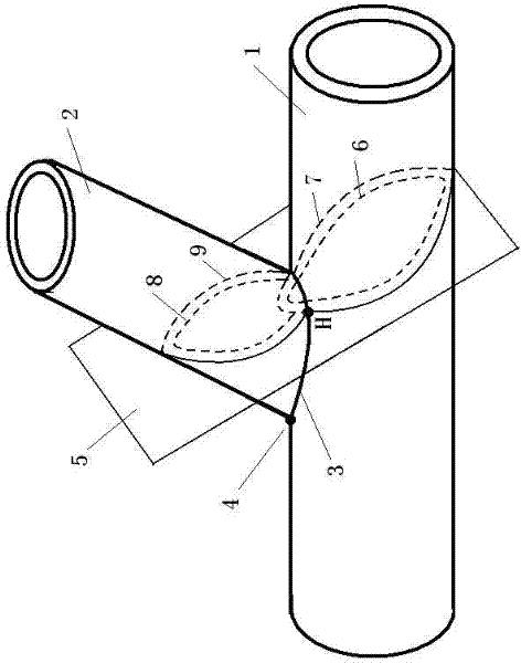
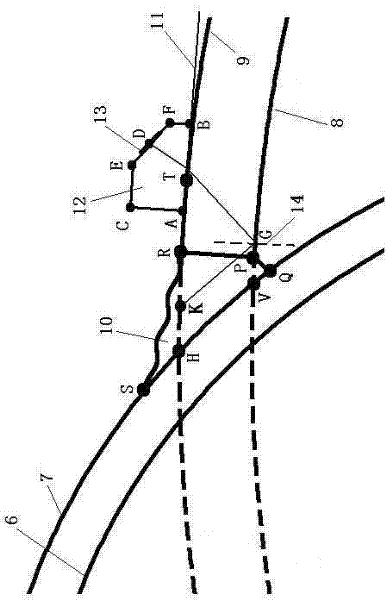
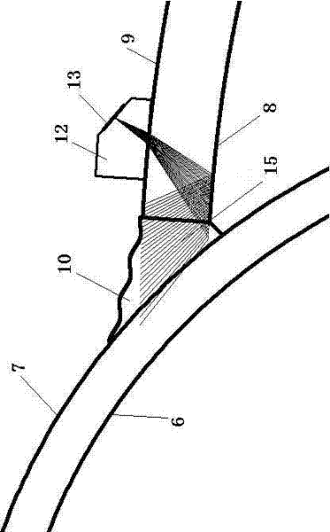
[0043] see figure 1 , to measure a Y-shaped pipe joint weld, first measure the outer diameter of the actual workpiece main pipe 1 is 410mm, the wall thickness of main pipe 1 is 13mm, the outer diameter of branch pipe 2 is 308mm, the wall thickness of branch pipe 2 is 20mm, the intersection of main pipe 1 and branch pipe 2 The angle is 60 degrees. Select a point H on the intersecting line 3 where the main pipe 1 and the branch pipe 2 intersect. The distance between this point and the toe 4 of the pipe node in the circumferential direction of the branch pipe is 245mm. Cross point H to make the legal surface 5 of the intersecting line 3, the legal surface intersects with the inner and outer walls of the main pipe 1 to obtain the intersection line 6 and the intersection line 7 respectively, and intersects with the inner and outer walls of the branch pipe 2 to obtain the intersection line 8 and the intersection line 9, respectively, and the intersection line 6 , 7, 8, and 9 are th...

Embodiment 2

[0053] see Figure 4 , to measure a T-shaped pipe joint, first measure the outer diameter of the actual workpiece main pipe 1 is 218mm, the wall thickness of main pipe 1 is 18mm, the outer diameter of branch pipe 2 is 168mm, the wall thickness of branch pipe 2 is 16mm, and the intersection angle between main pipe 1 and branch pipe 2 is 90 degrees. Select a point H on the intersecting line 3 where the main pipe 1 and the branch pipe 2 intersect. The distance between this point and the toe 4 of the pipe node in the circumferential direction of the branch pipe is 60mm. Cross point H to make the legal surface 5 of the intersecting line 3, the legal surface intersects with the inner and outer walls of the main pipe 1 to obtain the intersection line 6 and the intersection line 7 respectively, and intersects with the inner and outer walls of the branch pipe 2 to obtain the intersection line 8 and the intersection line 9, respectively, and the intersection line 6 , 7, 8, and 9 are th...


PUM


Abstract

The invention discloses a TKY pipe joint welding seam phased array ultrasonic beam covering method, the steps are as follows: according to the physical size of the pipe joint welding seam, the section figure at the specific position of the pipe joint is obtained; the weld joint outline is drawn in the obtained section picture; Obtain the phased array probe length, front length, height, inclination angle, and array element center height; select the incident point of the main sound beam of the array element on the ellipse of the outer wall of the branch pipe of the obtained graphic, and make the tangent line of the ellipse of the outer wall of the branch pipe at this point; the determined incidence The point is the elliptical contact point between the outline of the phased array probe and the outer wall of the branch pipe, and the tangent direction is the length direction of the phased array probe. Draw the outline of the phased array probe and draw the position of the array element; select the sound beam drawing method to draw the sound beam line. The invention contributes to the evaluation of the blind area of ​​TKY pipe joint weld ultrasonic detection, determines the coverage state of the ultrasonic beam on the pipe joint welding joint, effectively reduces the probability of missed detection or misjudgment of pipe joint detection, and contributes to the phase control of the TKY pipe joint weld Process design and defect assessment for array ultrasonic testing.

Description

technical field [0001] The invention relates to a phased array ultrasonic beam covering method for weld seams of TKY pipe joints, belonging to the field of non-destructive testing. Background technique [0002] In the steel structure bearing various loads, one end of the branch pipe is welded to the main pipe (the diameter of the branch pipe is smaller than or equal to the pipe diameter of the main pipe). In order to ensure the welding quality, a bevel is made at one end of the branch pipe. This structural form is called a pipe joint. welds. If the included angle between the main pipe and the branch pipe θ<90°, it is called Y joint weld. The included angle θ=90° of the main branch is called the T-joint weld. On the main assembly process line (outer diameter axis), two symmetrical branch pipes are welded according to the designed distance to form two Y-shaped joint welds symmetrical to the process line, called K joint welds. Pipe T, K, and Y-shaped welds are very prone ...

Claims


Application Information

Patent Timeline
Patent Type & Authority Applications(China)
IPC IPC(8): G01N29/265
Inventor 陆铭慧刘勋丰程俊
Owner NANCHANG HANGKONG UNIVERSITY
Why Eureka
Try Eureka