
Rubber sealing ring surface defect detection method based on machine vision

A rubber sealing ring and defect detection technology, applied in the field of detection, can solve the problems of disadvantageous defect detection, low light intensity, and reduced detection accuracy.

Pending Publication Date: 2020-05-12
BEIJING UNIV OF TECH
View PDF0 Cites 17 Cited by
  • Summary
  • Abstract
  • Description
  • Claims
  • Application Information

AI Technical Summary

Problems solved by technology

The segmentation algorithm is affected by the gray level difference between the object and the background. If the gray level difference between the object and the image background is not large due to low light intensity, dark background, rough bottom surface of the loading object, etc., the segmentation result will be affected. Detrimental to defect detection;
[0010] (3) Calculation error - any part of the surface of the O-ring is not flat, but has a certain curvature, so the actual size of a pixel block on the sealing ring image is not necessarily the same as the pixel size converted according to the calibration parameters Similarly, the sizes of any two pixels are not the same, which will lead to area calculation errors;
[0011] (4) Poor robustness and insufficient intelligence—the region segmentation method often makes the image over-segmented, and the edge detection is sensitive to noise points, which is prone to false edges, so the O-ring surface defect detection algorithm based on image segmentation often Dust, tiny debris and even image noise on the surface of the sealing ring will be regarded as an area of ​​interest and identified as a "defect", or because it is difficult to accurately identify an uncommon defect site and identify it as "normal", it will cause false alarms Or false positives, reducing the detection accuracy

Method used


Image

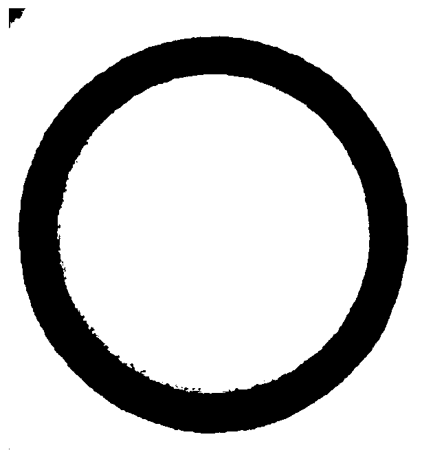
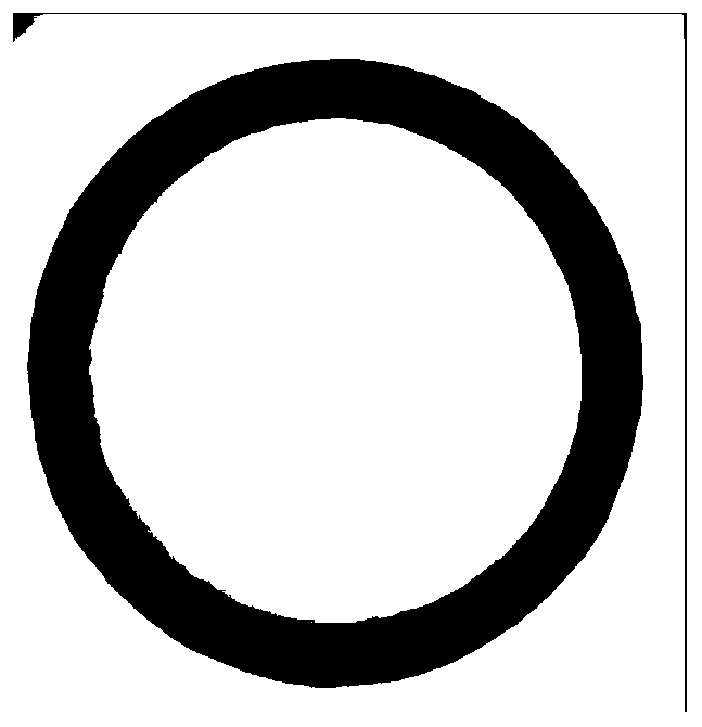
  • Rubber sealing ring surface defect detection method based on machine vision
  • Rubber sealing ring surface defect detection method based on machine vision
  • Rubber sealing ring surface defect detection method based on machine vision

Examples


Embodiment Construction

[0075] 1) Preparation

[0076] Real-time detection environment: O-ring rubber sealing ring surface defect detection algorithm runs on the sealing ring production line, and related equipment includes computers, high-precision CCD line scan industrial cameras, loading platforms, bowl-shaped LED light sources, etc. The industrial camera communicates with the computer and transmits data through the universal serial bus (USB). In order to eliminate the influence of stray light such as production environment lighting as much as possible, a dark room should be set up; in order to realize automatic detection, an external trigger mechanism is used in the acquisition system. Both the camera and the light source are located above the loading platform. Whenever the sealing ring to be detected on the industrial computer moves directly below the camera and the light source, the external trigger mechanism will send a signal to the camera. After the camera receives an effective trigger signal...


PUM


Abstract

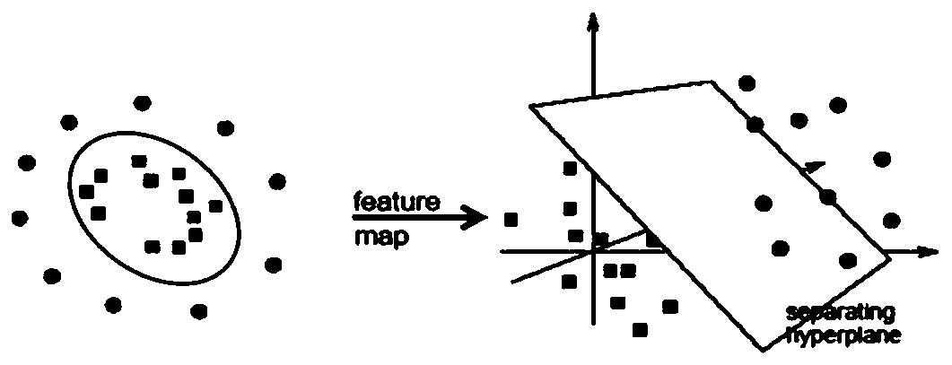
The invention relates to a rubber sealing ring surface defect detection method based on machine vision, and belongs to the field of detection. The invention designs a novel sealing ring surface defectmethod aiming at the defects of poor universality, easiness in missing detection and false detection and the like of a defect detection mode in an automatic detection link based on machine vision onan O-shaped rubber sealing ring production line. According to the method, a data driving strategy is adopted, image texture features extracted by Gabor filters of different scales and in different directions are integrated and combined with a support vector machine (SVM), an image preprocessing technology and feature dimension reduction are assisted, and a classifier capable of accurately identifying the surface defects of the O-shaped rubber sealing ring is trained. The classifier can effectively reduce the missing detection rate and the false detection rate of a traditional Blob detection method (image preprocessing, image segmentation, region of interest separation and defect recognition), and is higher in universality.

Description

technical field [0001] The invention relates to a method for detecting surface defects of a rubber sealing ring based on machine vision, and belongs to the field of detection. Background technique [0002] Rubber sealing ring is a basic industrial component, which is widely used in military and civilian fields such as equipment manufacturing, automobiles, robots, and aerospace. Its sealing principle is to deform under the action of pressure, so that the edge is close to the sealing surface, the higher the pressure, the tighter the edge and the sealing surface are, and the seal is realized. The cost of rubber sealing ring is low, the production threshold is low, the process is mature, and the production process has achieved a high yield rate, but there are also defects such as air bubbles, flashes, edge burrs, missing rubber, dirt, and incidental impurities. These defective products There are potential safety hazards in use, which may cause economic and even loss of life and...

Claims


Application Information

Patent Timeline
IPC IPC(8): G06T7/00G06T5/00G06K9/40G06K9/62
CPCG06T7/0004G06T2207/10016G06T2207/10024G06T2207/20024G06T2207/20032G06T2207/20081G06T2207/30108G06V10/30G06F18/2135G06F18/2414G06F18/2411G06T5/70
Inventor 沈琦许伯睿
Owner BEIJING UNIV OF TECH
Learn More