Hybrid excitation synchronous starting system and method of synchronous motor
An excitation system and synchronous start technology, applied in the direction of the starting device, etc., can solve the problems of synchronous brushless electric excitation generator and synchronous brushless electric excitation motor, etc., and achieve simplified towing test equipment and large excitation Current adjustment range, output power smooth and continuous effect
- Summary
- Abstract
- Description
- Claims
- Application Information
AI Technical Summary
Problems solved by technology
Method used
Image
Examples
Embodiment 1
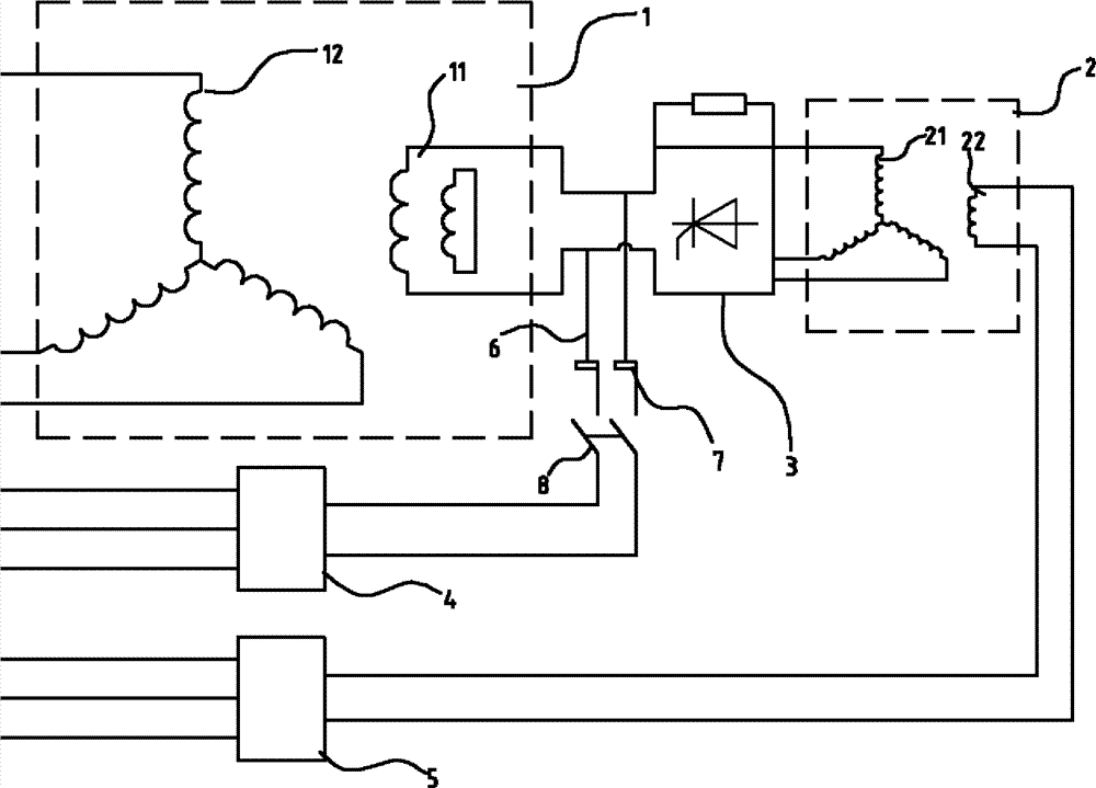
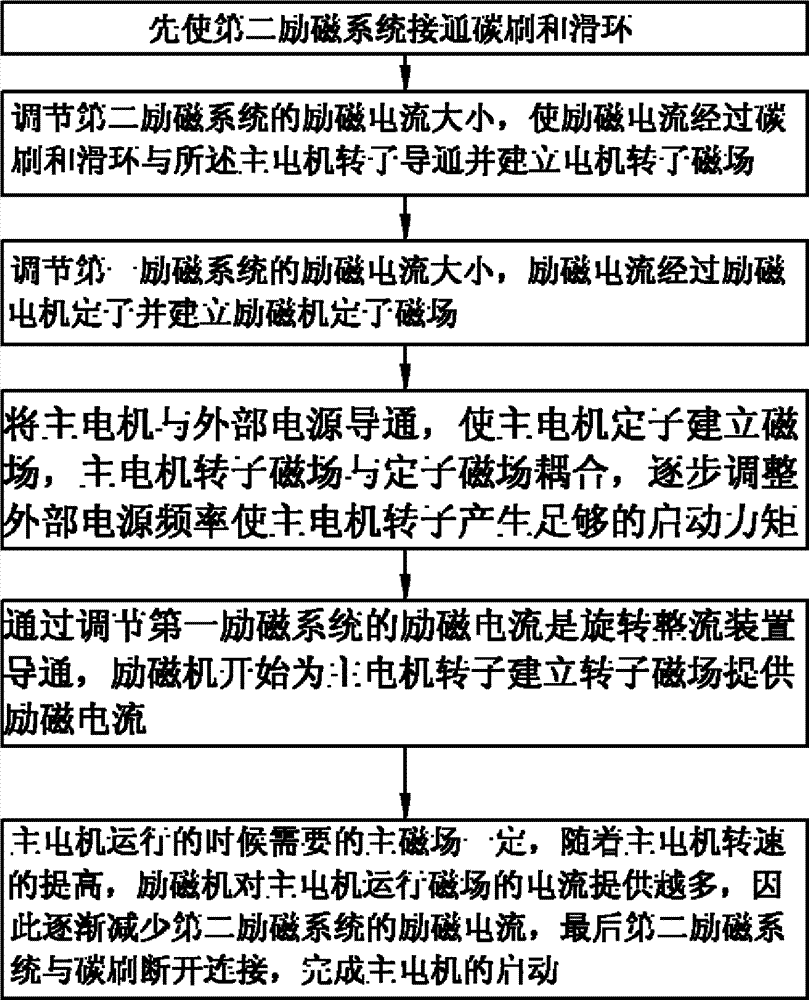
[0035] A synchronous start-up system for compound excitation of a synchronous motor, comprising a main motor 1, an exciter 2, a rotating rectifier 3, a first excitation system 5 and a second excitation system 4; the main motor rotor 11, the exciter rotor 21 and the rotating rectifier Disk 3 is synchronized. In this embodiment, the first excitation system 5 and the second excitation system 4 are excitation cabinets, which are convenient for transportation and deployment. The rotating rectifier disc 3 controls the conduction angle of the diode by a thyristor, thereby changing the overcurrent capability of the diode; the first excitation system 5 provides excitation current to the stator of the exciter 2; the rotor of the exciter 2 passes through The rotating rectifying disc 3 provides excitation current to the rotor of the main motor 1 . A synchronous slip ring 6 is provided between the rotating rectifier disc 3 and the rotor of the main motor 1, and the slip ring 6 rotates wit...
Embodiment 2
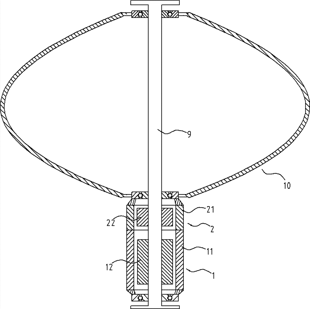
[0046] Such as figure 1 , 3 As shown, a vertical axis wind power generator includes a tower column 9, a wind wheel 10 located on the tower column 9, a main motor 1 and an exciter 2, the main motor 1 and the exciter 2 are external rotor structures, and the main motor The stator 12 and the exciter stator 22 hug the tower 9 tightly, and the wind wheel 10 , the rotor 11 of the main motor and the rotor 21 of the exciter are connected into one body and can rotate around the tower 9 synchronously. A rotating rectifying device is provided between the main motor 1 and the exciter 2. This embodiment is a rotating rectifying disc 3. The rotating rectifying device controls the conduction angle of the diode by a silicon controlled rectifier, thereby changing the overcurrent capability of the diode. The rotating rectifying device and the Main motor, rotor 11 and exciter rotor 21 are synchronized. The exciter 2 is controlled by a first excitation system 5 which supplies an excitation curre...
PUM
 Abstract
Description
Claims
Application Information
 - R&D
- Intellectual Property
- Life Sciences
- Materials
- Tech Scout
- Unparalleled Data Quality
- Higher Quality Content
- 60% Fewer Hallucinations
Browse by: Latest US Patents, China's latest patents, Technical Efficacy Thesaurus, Application Domain, Technology Topic, Popular Technical Reports.
© 2025 PatSnap. All rights reserved.Legal|Privacy policy|Modern Slavery Act Transparency Statement|Sitemap|About US| Contact US: help@patsnap.com


