Mold and method for making multilayer plastic molded parts

A technology for molded parts and plastics, which is used in the field of manufacturing multi-layer plastic molded parts, and can solve the problems of inability to form back incisions, surface structural limitations, etc.

Active Publication Date: 2011-12-21
COVESTRO DEUTSCHLAND AG
View PDF15 Cites 5 Cited by
  • Summary
  • Abstract
  • Description
  • Claims
  • Application Information

AI Technical Summary

Problems solved by technology

The disadvantage of this method is that the surface structuring is limited by the properties of the film, it is not possible to form a back cut, because the insertion and thermoforming of the film requires additional processing steps and the parting film has to be removed as waste after a certain period of time

Method used


Image

  • Mold and method for making multilayer plastic molded parts
  • Mold and method for making multilayer plastic molded parts
  • Mold and method for making multilayer plastic molded parts

Examples


Embodiment Construction

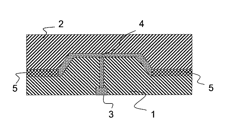
[0046] figure 1 An injection mold for producing a substrate is shown, consisting of a first mold half (1) and a second mold half (2). The base material is injected into the base material cavity (4) through the sprue (3). There are separate mold inserts (5) next to the substrate cavity side.

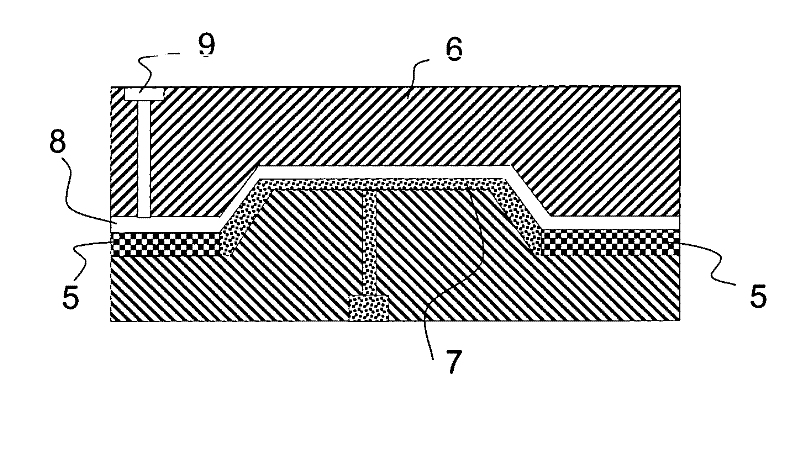
[0047] After the base material has reached a sufficiently high strength, the second half-mold (2) is replaced by the third half-mold (6) ( figure 2 ). The third mold half (6), the parting insert (5) and the hardened base material (7) now form the cavity (8) for the paint. An external parting agent may have to be applied to the inner surface of the mold half (6), but not to the parting insert. Through the gating system (9), lacquer is injected into the mold cavity to form the coating layer (8).

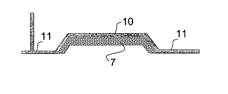
[0048] After the paint hardens, image 3 The illustrated coated components (moldings) can be demoulded. The molded part consists of a base material (7), a paint (10) and a side gate stub ...


PUM


Abstract

The invention relates to a mould for producing multi-layer shaped parts of plastic comprising at least two mould halves (1, 2, 6) and a cavity (4), in which the plastic is held, a gating system (9) with a runner and an exchangeable separating mould insert (5), as well as a method for producing the multi-layer shaped parts of plastic.

Description

technical field [0001] The invention relates to a mold for producing multilayer plastic moldings comprising at least two mold halves and a cavity in which the plastic is accommodated and a gating system with runners, the invention also relates to a mold for producing multilayer plastic moldings method of the piece. Background technique [0002] The production of multilayer plastic moldings is known from the prior art. EP197496B describes a method in which a substrate is injected between two separable molding halves. Once the substrate has hardened sufficiently, the coating is injected at a pressure significantly higher than the mold cavity pressure and is therefore rigid over the entire surface of the substrate or over partial areas of the surface. [0003] A method of coating components on the exposed side is described in DE4316154C. In this method, an uncoated component is placed into a forming mold similar to that used in injection molding, and then resin or lacquer is...

Claims


Application Information

Patent Timeline
Patent Type & Authority Applications(China)
IPC IPC(8): B29C33/00B29C33/30B29C33/56B29C45/26B29C45/37B29C45/27B29C33/60B29C37/00B29C45/14B29C45/16
CPCB29C33/306B29C45/1679B29C33/56B29C45/2673B29C45/2711B29C33/68B29C45/14B29C45/37B29C33/60B29C37/0028B29C45/16B29C33/0061
Inventor H.埃宾D.布吕宁R.普罗特
Owner COVESTRO DEUTSCHLAND AG
Why Eureka
Try Eureka