Convertible shoe body

A shoe upper and shoe body technology, applied in footwear, clothing, applications, etc., can solve problems such as cost consumption, increased component defect rate, and increased number of molds, so as to reduce molds and consumables, reduce outsole defect rate, and improve The effect of production efficiency

Inactive Publication Date: 2011-12-28
杨成义
View PDF4 Cites 5 Cited by
  • Summary
  • Abstract
  • Description
  • Claims
  • Application Information

AI Technical Summary

Problems solved by technology

[0003] 1. Due to the variety of shapes of the outsole 10, the shape of the catch seat 11 fixed on the top also changes accordingly. As a result, if the industry wants to form the catch seat 11 of different shapes, it must make different processing molding molds. When there are many shapes of the latch seat 11, the number of molds will increase relatively, resulting in a costly loss
[0004] 2. Since each locking seat 11 is integrally formed, and there are rows of accommodating spaces 112 and positioning pieces 113 on both sides or one side, but only the positioning pieces 113 can be used for the buckle 21 of the shoe upper 20 to be locked. Button assembly, other parts of the panel will form unnecessary consumables, resulting in increased cost of missing
[0005] 3. Since each locking seat 11 is fixed on the outsole 10 by injection molding or bonding, it is easy to be fixed on the outsole 10 due to factors such as manual operation or poor bonding technology, and the locking seat 11 is deflected and fixed on the outsole 10. Unable to snap and assemble the buckle 21 of the shoe upper 20, so that the outsole 10 and the buckle seat 11 must be discarded as a whole, resulting in an increase in component defect rate and costly loss
[0006] 4. Since each catch seat 11 is exposed on the top surface of the outsole 10, in order to keep the surface of the outsole 10 flat, an additional midsole 30 must be made, and the midsole 30 must be fixed on the outsole 10 to facilitate Can cover multiple card sockets 11, resulting in loss of increased cost

Method used


Image

  • Convertible shoe body
  • Convertible shoe body
  • Convertible shoe body

Examples


Embodiment Construction

[0039] In order to enable your examiner to have a better understanding of the present invention, hereby cite a preferred embodiment together with the accompanying drawings, and describe it in detail as follows:

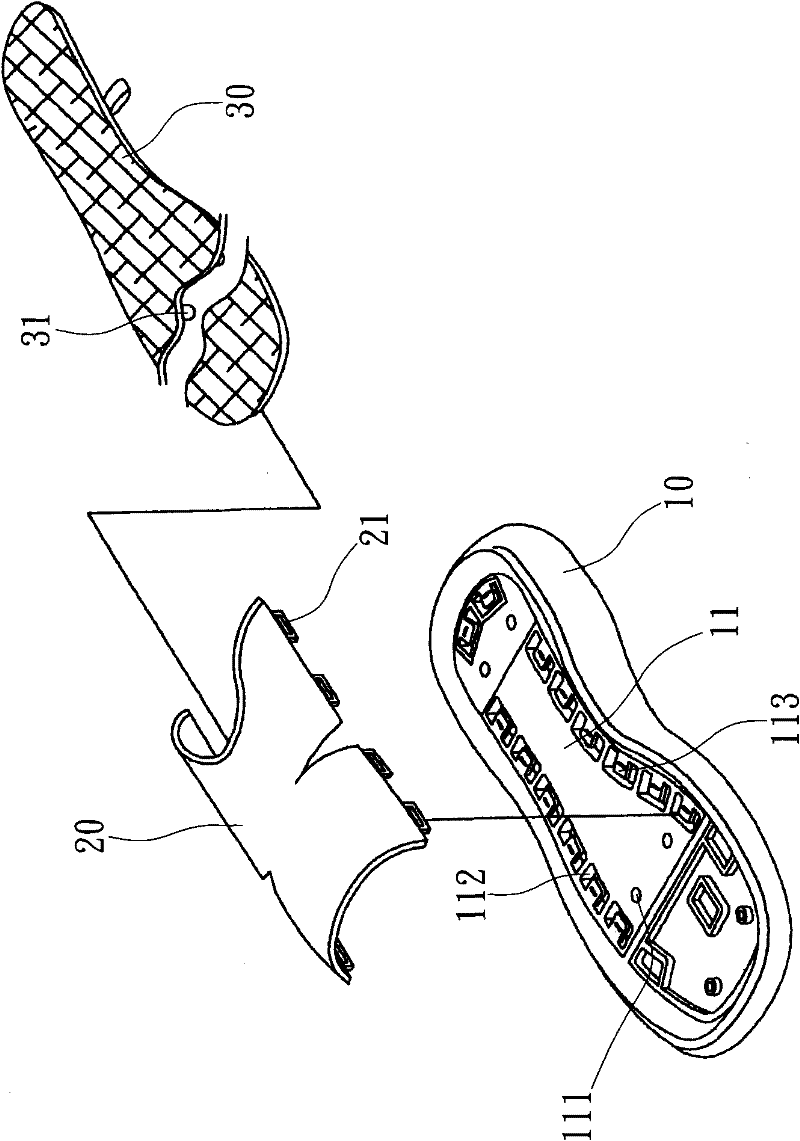
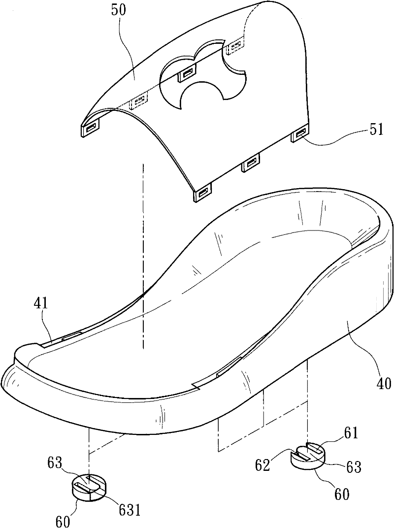
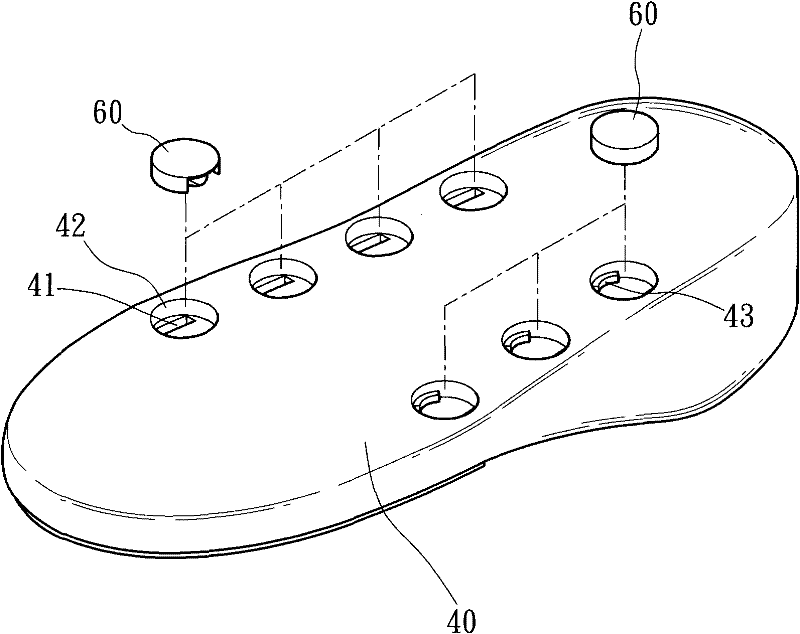
[0040] see figure 2 , image 3 The shoe body of the present invention includes a large bottom 40, a vamp 50 and a plurality of positioning parts 60. The large bottom 40 is a shoe shape and can be made of different materials. In this embodiment, the large bottom 40 is The rubber material is integrally injection-molded, and a plurality of perforations 41 through the bottom surface are provided on both sides of the top surface, and grooves 42 are provided on the bottom surface corresponding to the positions of the perforations 41. In this embodiment, each groove 42 is roughly It is circular, and the inner ring surface has an appropriate slope, and an arc-shaped guide block 43 is protruded on the inner top surface. The shoe upper 50 can be in different shapes. In this e...


PUM


Abstract

The invention discloses a shoe body with a replaceable vamp. The shoe body comprises an undersole, a vamp and a plurality of positioning pieces, wherein the circumferences of both sides of the top surface of the undersole are provided with a plurality of through holes leading to a bottom surface; grooves are formed at positions on the bottom surface corresponding to the through holes; fasteners are arranged at positions on two side bottom surfaces of the vamp corresponding to each through hole of the undersole, are inserted into the through holes, and project out of the grooves; a plurality of positioning pieces with clamping blocks are used for buckling the fasteners on the vamp with the clamping blocks and are arranged in the grooves of the undersole; and the vamp can be assembled and positioned above the undersole to quickly form a shoe body. Vamps and undersoles of different styles can be matched by using the positioning pieces, so that the using quantity of molds and consumptive materials is reduced, the fraction defective of the undersole is lowered, and the practical effects of effectively saving cost and increasing the production efficiency are achieved.

Description

technical field [0001] The invention relates to a shoe body capable of reducing molds and consumables, and reducing component defective rate, so as to effectively save costs and improve production efficiency. Background technique [0002] Nowadays, sandals, casual shoes and other shoe bodies not only pay attention to the diversification of shapes, but also focus on the functionality of use, so some companies design a shoe body with replaceable upper type, please refer to figure 1 , the shoe body includes a outsole 10, a vamp 20 and a midsole 30, the outsole 10 is made of rubber material, and a plurality of buckles made of plastic materials are fixed on the top surface by injection molding or bonding Seat 11, each locking seat 11 has different shapes according to the type of outsole 10 to be assembled, and is provided with a plurality of positioning holes 111, and is provided with a plurality of accommodating spaces 112 along the periphery, and in each accommodating space 112...

Claims


Application Information

Patent Timeline
Patent Type & Authority Applications(China)
IPC IPC(8): A43B3/06A43B3/24A43B9/00
Inventor 杨成义
Owner 杨成义
Why Eureka
Try Eureka