
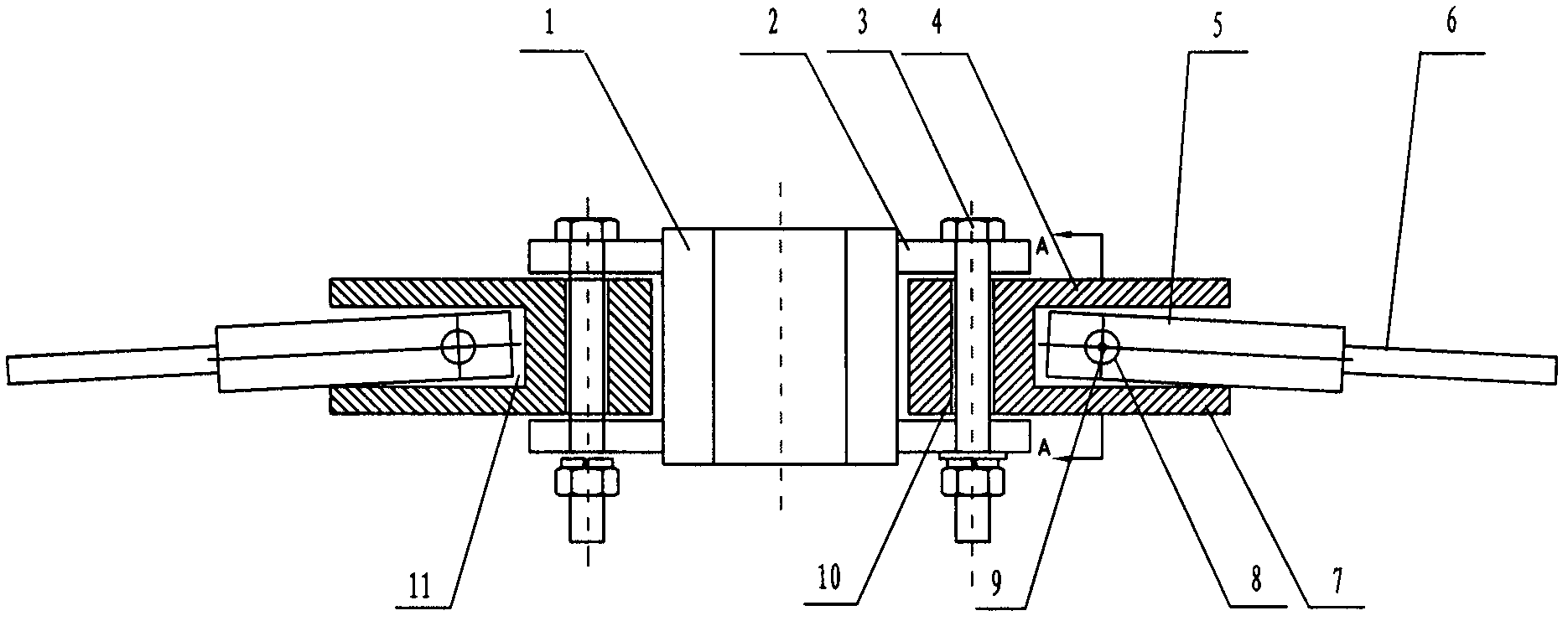
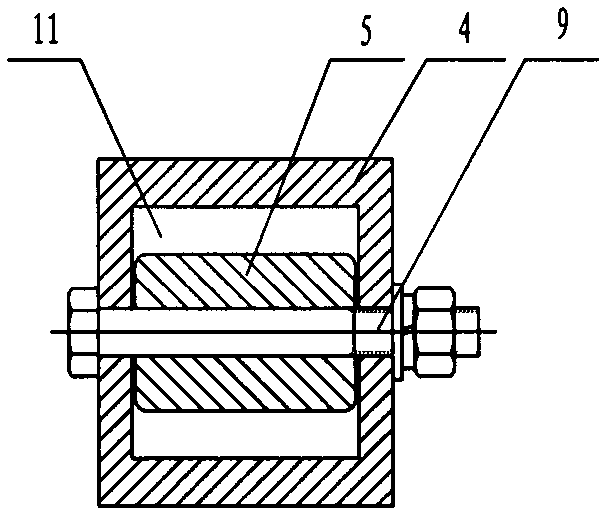
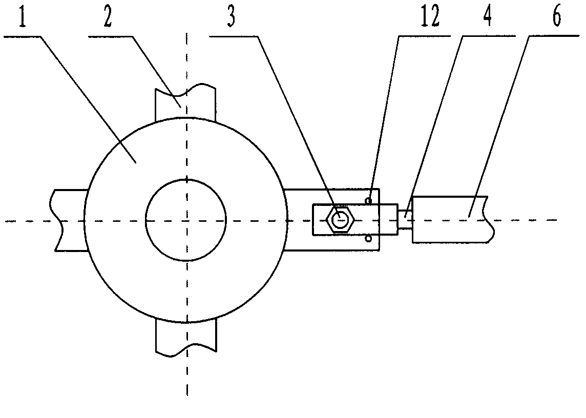
Axial impeller with vanes and hubs in composite hinge

A technology of axial-flow impeller and composite hinge, which is applied to components of pumping devices for elastic fluids, non-variable pumps, machines/engines, etc., to achieve the effects of improved reliability, simplified structure, and extended service life

Active Publication Date: 2013-09-18
WEIHAI CREDITFAN VENTILATOR
View PDF2 Cites 0 Cited by
  • Summary
  • Abstract
  • Description
  • Claims
  • Application Information

AI Technical Summary

Problems solved by technology

However, this structure only eliminates the bending moment in the vertical direction, and the bending moment generated in the rotation plane still exists, so it is not a true zero bending moment impeller

Method used


Image

  • Axial impeller with vanes and hubs in composite hinge
  • Axial impeller with vanes and hubs in composite hinge
  • Axial impeller with vanes and hubs in composite hinge

Examples


Embodiment 1

[0014] Embodiment 1: The rotating shaft of the impeller is vertical to the ground, and the blades discharge air upward or downward.

[0015] Impeller diameter D=3m, hub diameter d=0.3m, power N=7.5kW, speed n=260r / min, blade mass M=8kg, number of blades Z=4, total pressure P=115Pa.

[0016] Calculated: angular velocity ω=n×π / 30=27.2rad / s, blade center of gravity radius R=(D+d) / 4=0.825m, blade center of mass position L1=0.675m, blade aerodynamic center position L2=1.01m.

[0017] Gravity W=mg=78.4N,

[0018] Aerodynamic force F2=(π×D 2 ×P / 4) / Z=203N,

[0019] Centrifugal force F3=M×R×ω 2 =4883N,

[0020] Air resistance F4=9551N / (n×L2×Z)=68.2N

[0021] When the wind is discharged upwards, the downward swing angle of the blade is α=arc tg(W+1.5F2) / F3=4.5°, and the left and right swing angle of the blade is β=arc tg(1.5F4 / F3)=1.2°.

[0022] The upward swing angle of the downward exhaust air blade is α=2.6°, and the left and right swing angle of the blade is β=1.2°.

Embodiment 2

[0023] Embodiment 2: The rotating shaft of the impeller is vertical to the ground, and the blades discharge wind upward or downward.

[0024] D=9.2m, d=1.5m, N=200KW, n=127r / min, M=65kg, Z=10, P=175Pa

[0025] Calculated: ω=13.3rad / s, R=2.675m, L1=1.925, L2=2.888.

[0026] Calculated by the formula in Example 1: W=637N, F2=1163N, F3=30757N, F4=521N.

[0027] When the wind is discharged upwards, the downward swing angle of the blade is α=4.4°, and the left and right swing angle β=1.5°;

[0028] When the air is exhausted downward, the angle α=2.1° that the blade swings upwards=2.1°, and the angle β=1.5° that swings left and right.

Embodiment 3

[0029] Embodiment 3, the rotating shaft of the impeller is parallel to the ground, and the air is exhausted horizontally.

[0030] In the case of horizontal exhaust, the α angle of the up and down swing is smaller than the upward exhaust and greater than the downward exhaust, so there is no need to calculate it, and the β angle of the left and right swing is sufficient. However, when the β angle rotates 360°, the β value is different at different positions, and now only the maximum and minimum values ​​are calculated.

[0031] β=arc tg{9551N / [(n×L1×Z)±W] / F3}.

[0032] The impeller D=3m, βmax=2.1°, βmin=0.28°.

[0033] The impeller D=9.2m, βmax=2.6°, βmin=0.26°.


PUM


Abstract

The invention discloses an axial impeller with vanes and hubs in composite hinge, comprising the hubs, the vanes and vane joints connected with the connecting ends of the vanes. The axial impeller has the key points that the hubs are provided with at least two composite hinge devices with zero bending moment; each composite hinge device is provided with a vertical shaft hole and a horizontal shaft hole; a joint of double lugs of each hub is hinged with each vertical shaft hole through a vertical shaft; the vane joints are hinged with the horizontal shaft holes through horizontal shafts; the vanes have a downward swinging angle less than or equal to 5 DEG, an upward swinging angle less than or equal to 3 DEG and a left and right swinging angle less than or equal to 3 DEG. In the invention,two bending moments at the roots of the vanes are eliminated, the problem that the roots of the vanes of a large axial flow fan is easy to crack is solved, the structure is optimized, the weight is reduced, the production cost is reduced, the service life of the large axial flow fan is prolonged, and meanwhile, the quality is ensured. The axial impeller in composite hinge can be widely installed and used on equipment such as a large evaporative condenser, a large air-cooling tower and the like.

Description

Technical field [0001] The invention relates to the technical field of fans, in particular to a large axial flow fan impeller with no bending moment at the blade root. Background technique [0002] Large air volume axial flow fans are extremely versatile. However, this type of fan has a large load and long blades. In addition, the blades and the hub are usually fixedly connected by welding, riveting, and bolts. Two mutually perpendicular bending moments reach their maximum at the blade root. This bending moment is particularly prominent on large-size impellers, so that structural fractures of the blades occur. Taking the impeller of a large axial flow fan with a diameter of 10m as an example, the bending moment in the vertical direction at the root of the blade can reach more than 8000N.m. In order to meet the strength requirements of fan blades, the traditional method is to design the structural section of the blade root to be very large and strong, and generally use str...

Claims


Application Information

Patent Timeline
Patent Type & Authority Patents(China)
IPC IPC(8): F04D29/32
Inventor 盛才良王新盛军岭
Owner WEIHAI CREDITFAN VENTILATOR
Learn More