Boiler drum longitudinally arranged chain grate hot water boiler
What is AI technical title?
AI technical title is built by Patsnap AI team. It summarizes the technical point description of the patent document.
A chain grate and hot water boiler technology, which is applied in the field of hot water boilers, can solve the problems of easy blockage of pipes, low heat efficiency of boilers, large coal consumption, etc. large area effect
Active Publication Date: 2013-06-05
HARBIN TIANDIKUAN ENERGY SAVING TECH
View PDF7 Cites 0 Cited by
Summary
Abstract
Description
Claims
Application Information
AI Technical Summary
This helps you quickly interpret patents by identifying the three key elements:
Problems solved by technology
Method used
Benefits of technology
Problems solved by technology
[0003] The purpose of the present invention is to solve the problems of low thermal efficiency, large coal consumption, easy blockage of pipes and high exhaust gas temperature of the existing boilers, and further provide a vertical boiler drum type chain grate hot water boiler
Method used
Image
Click on the blue label to locate the original text in one second.
Reading with bidirectional positioning of images and text.
Examples
specific Embodiment approach 1
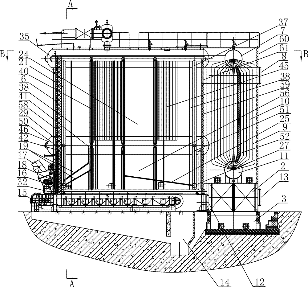
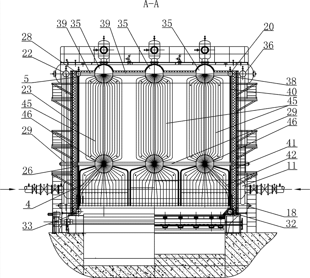
[0015] Specific implementation mode one: combine Figure 1 ~ Figure 4Describe this embodiment, the drum vertical chain grate hot water boiler in this embodiment includes a furnace body 6, a layered coal feeder 16, a coal feeder 17, a large beam chain grate 15, a front arch 57, and a rear arch 54 , the left anti-coking box 33, the right anti-coking box 32, a plurality of upper drums 35 and a plurality of lower drums 46 consistent with the number of the upper drums, the bottom of a plurality of upper drums 35 is the furnace 24, the The lower rear end of the large beam chain grate 15 is provided with a slag outlet 14, and the coal feeder 17 is arranged in front of the front wall 58 of the furnace body and directly above the input end of the large beam chain grate 15, and the layered coal feeder 16 is set between the coal feeding hopper 17 in front of the front wall 58 of the furnace body and the input end of the large beam chain grate 15, and the output end of the large beam chai...
specific Embodiment approach 2
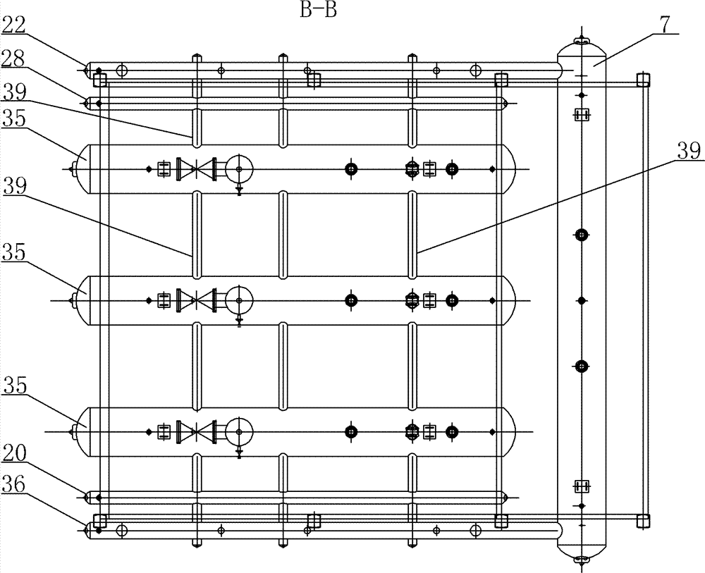
[0016] Specific implementation mode two: combination figure 1 Describe this embodiment, the convection economizer 9 described in this embodiment includes an upper cylinder 7, a lower cylinder 11 and a set of convection tube bundles 10, the upper end of the convection tube bundle 10 communicates with the upper cylinder 7, and the convection tube bundle 10 The lower end communicates with the lower cylinder 11, the lower cylinder 11 at the bottom of the convection economizer 9 communicates with the pipe network water collector, and the upper cylinder 7 of the upper part of the convection economizer 9 is respectively connected to one end of the left longitudinal water pipe 22 and One end of the right vertical water pipe 36 is connected, and a second baffle wall 52 is arranged longitudinally between the upper cylinder body 7 and the lower cylinder body 11 . With such a setting, the heating surface is large, it is not easy to deposit carbon and dust outside the convection tube bundl...
specific Embodiment approach 3
[0017] Specific implementation mode three: combination figure 1 and image 3 Describe this embodiment, the quantity of the upper drum 35 of this embodiment is 3-6. With such a setting, the heating area is large, the thermal efficiency of the boiler is high, and it is not easy to deposit carbon and dust outside the convection tube bundle, and there is no dirt in the convection tube bundle, avoiding the blockage of the convection tube bundle, and at the same time meeting the design requirements. Others are the same as in the first or second embodiment.
PUM
Abstract
The invention discloses a boiler drum longitudinally arranged chain grate hot water boiler, and relates to a hot water boiler to solve the problems that the conventional boiler has low thermal efficiency and high coal consumption, pipes are easy to block, and smoke discharging temperature is high. The boiler drum longitudinally arranged chain grate hot water boiler comprises a left longitudinal upper header, a right longitudinal upper header, a left longitudinal water tank, two first vertical water distributing pipes, two second vertical water distributing pipes, a plurality of upper transverse headers, a plurality of lower transverse headers, a front transverse header, a rear transverse header, a plurality of first water cooling wall pipes, a plurality of second water cooling wall pipes,a plurality of groups of third water cooling wall pipes, a plurality of groups of fourth water cooling wall pipes, a plurality of groups of fifth water cooling wall pipes, a plurality of groups of sixth water cooling wall pipes, a plurality of groups of upper convection banks, a plurality of groups of front convection banks, a plurality of groups of rear convection banks, and at least one convection economizer, wherein the front transverse header and the rear transverse header are communicated with a left coking prevention ark and a right coking prevention ark; adjacent upper boiler drums in a plurality of upper boiler drums, and the left longitudinal upper header and the right longitudinal upper header and the respectively adjacent upper boiler drums are communicated thorough the plurality of upper transverse headers. The boiler drum longitudinally arranged chain grate hot water boiler is used for central heating.
Description
technical field [0001] The invention relates to a hot water boiler. Background technique [0002] Most of the boilers currently produced are water-fire tube boilers with small heating area, low thermal efficiency, large coal consumption and high operating costs. The threaded smoke pipe is often blocked, and the smoke pipe needs to be cleaned every half a month. The labor intensity is high, and the furnace needs to be shut down for maintenance. Contents of the invention [0003] The purpose of the present invention is to solve the problems of low thermal efficiency, large coal consumption, easy blockage of pipes and high exhaust gas temperature of existing boilers, and further provide a vertically mounted boiler drum chain grate hot water boiler. [0004] The technical solution adopted by the present invention to solve the above-mentioned problems is: the drum vertical chain grate hot water boiler of the present invention includes a furnace body, a layered coal feeder, a c...
Claims
Application Information
Patent Timeline
Application Date:The date an application was filed.
Publication Date:The date a patent or application was officially published.
First Publication Date:The earliest publication date of a patent with the same application number.
Issue Date:Publication date of the patent grant document.
PCT Entry Date:The Entry date of PCT National Phase.
Estimated Expiry Date:The statutory expiry date of a patent right according to the Patent Law, and it is the longest term of protection that the patent right can achieve without the termination of the patent right due to other reasons(Term extension factor has been taken into account ).
Invalid Date:Actual expiry date is based on effective date or publication date of legal transaction data of invalid patent.

