
Heat exchanger

A heat exchanger and flat tube technology, applied in the field of heat exchangers, can solve problems such as low heat exchange efficiency, and achieve the effect of improving heat exchange efficiency and heat exchange efficiency

Active Publication Date: 2014-12-10
YJS
View PDF11 Cites 0 Cited by
  • Summary
  • Abstract
  • Description
  • Claims
  • Application Information

AI Technical Summary

Problems solved by technology

[0005] In addition, it is known that when fluid heat is exchanged through a flat tube, the heat exchange is not only related to the thermal conductivity of the flat tube, but also related to the surface area of ​​the flat tube and the flow velocity of the fluid flowing inside and outside the flat tube. , in the use of flat tubes with smooth surfaces in the past, there is still a problem of low heat exchange efficiency

Method used


Image

  • Heat exchanger
  • Heat exchanger
  • Heat exchanger

Examples


Embodiment Construction

[0029] Hereinafter, embodiments of the present invention will be described with reference to examples in the drawings.

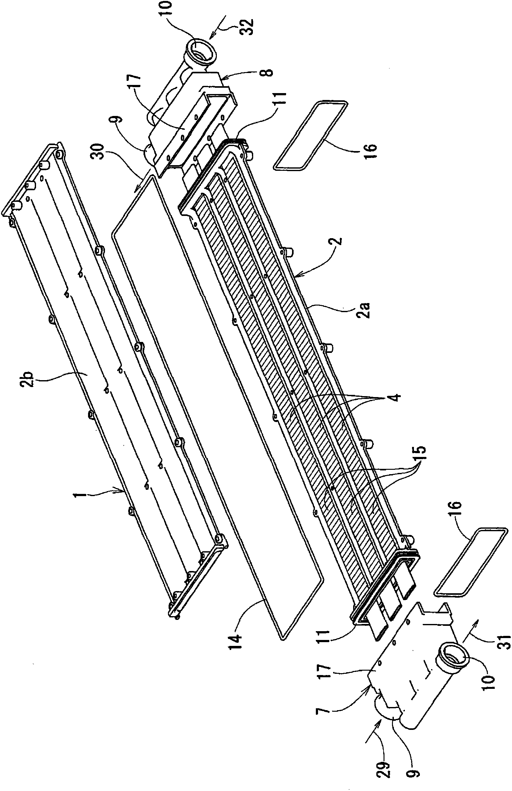
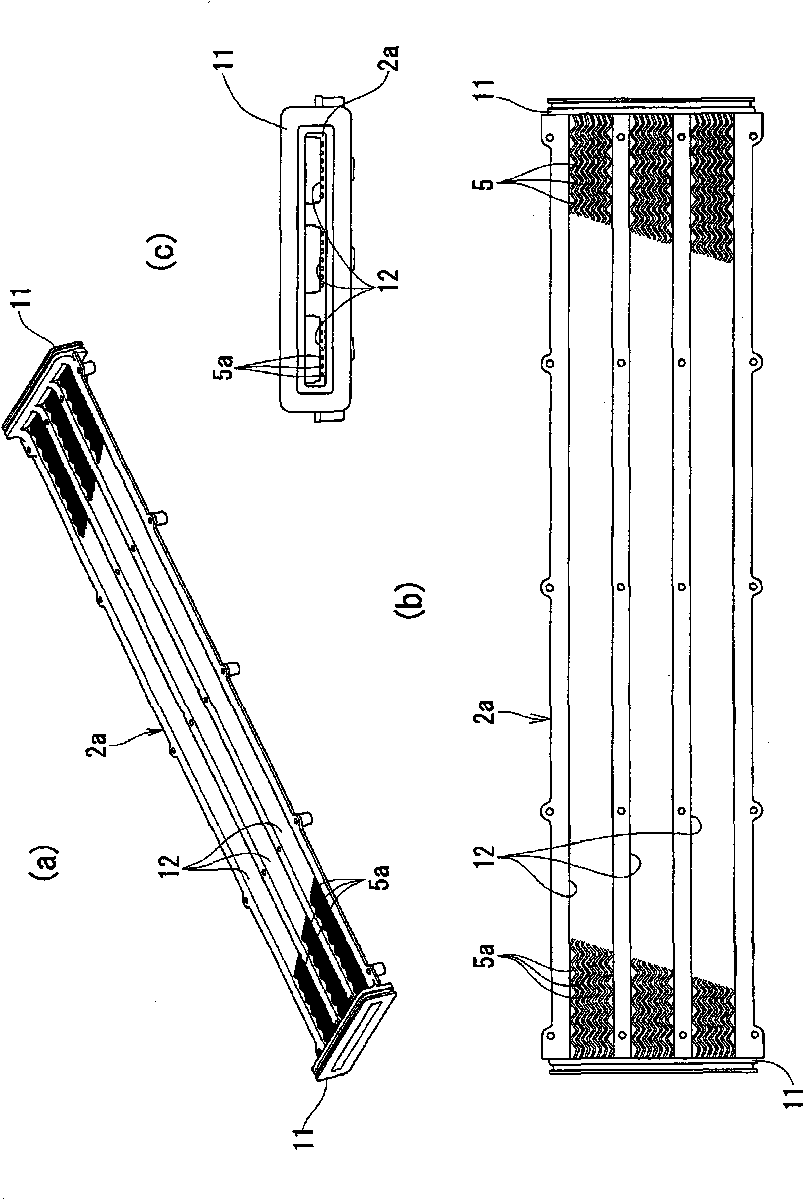
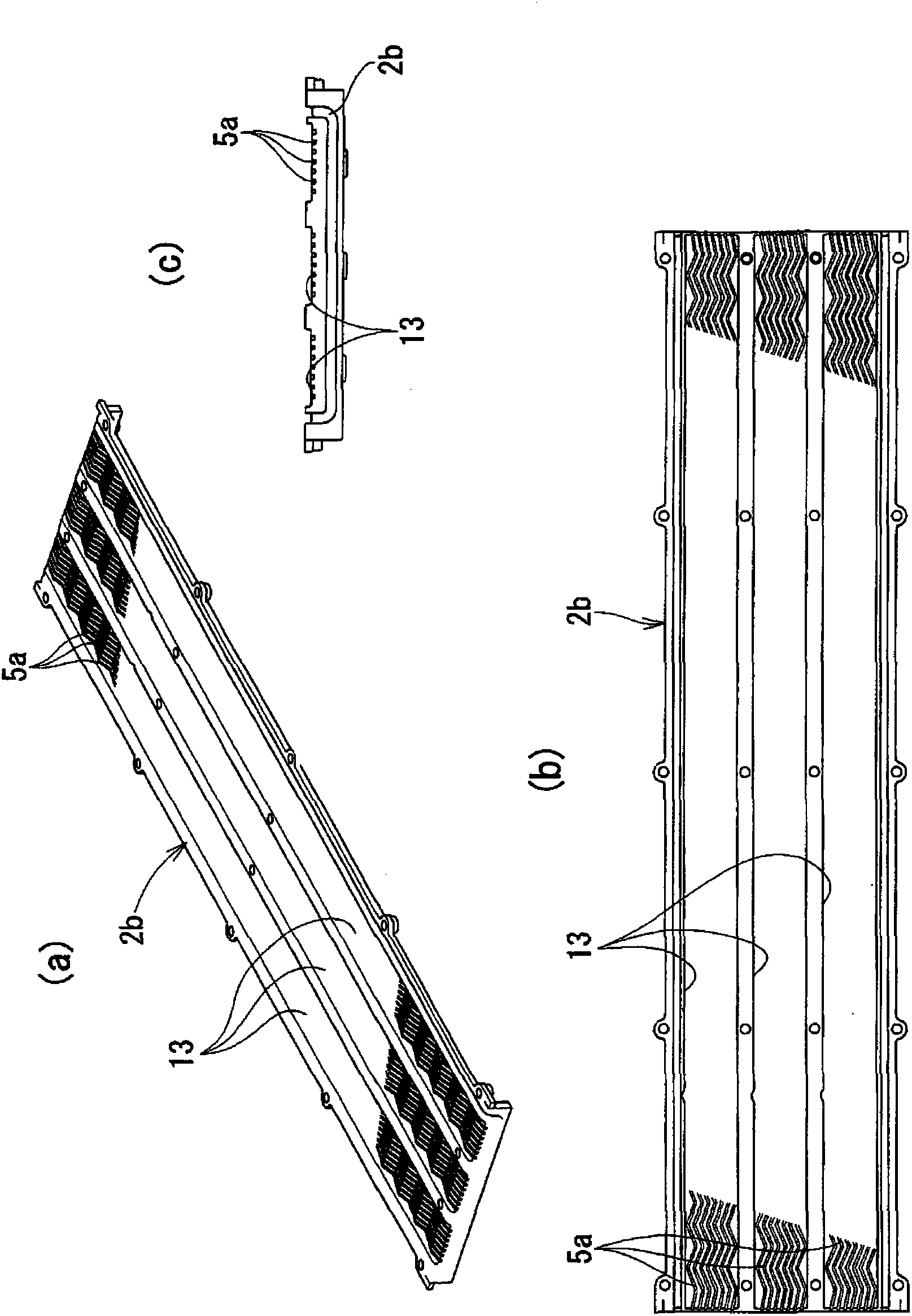
[0030] Figure 1 to Figure 6 Showing the first embodiment of the heat exchanger according to the present invention, the heat exchanger 1 forms three tubes penetrating the entire length of the outer case 2 in a parallel arrangement inside the flat and long outer case 2 . The flat tubes 4 are housed in each of the cylindrical housing parts 3. On the inner peripheral surface of the cylindrical housing part 3, there is formed a channel for allowing one of the fluids intended to exchange heat to flow along the flat tubes 4. The fluid passage 5 that flows in the longitudinal direction, and the inside of the flat tube 4 become the flow passage 6 through which the other fluid flows.

[0031] The fluid supply and discharge heads 7 and 8 are watertightly fixed to both ends of the outer casing 2, and the supply and discharge channels 9 of one side of the fluid supply ...


PUM


Abstract

A heat exchanger is provided of which the heat exchange efficiency is significantly improved by providing a flat tube with an increased surface area and increasing the flow speed of fluid that flows outside the flat tube. The heat exchanger includes an outer case (2) defining therein a tubular space (3), and a flat tube (4) received in the tubular space (3). A first fluid and a second fluid are fed through the tubular space, outside and inside the flat tube, respectively, to exchange heat between the first and second fluids. The flat tube (4), which defines a flow passage (6) therein, includes a peripheral wall having a surface increasing shape (15) which is in the form of a longitudinally continuous helical corrugation, longitudinally continuous corrugations, corrugations continuous in section in a width direction, or longitudinally extending fins formed on an outer surface of the peripheral wall of the flat tube so as to be spaced apart from each other in the width direction. Fluid passages (5) are defined by a large number of fluid flow rectifying grooves (5a) formed parallel to each other in the inner periphery of the tubular space (3) of the outer case (2).

Description

technical field [0001] The present invention relates to a flat plate heat exchanger for supplying hot water and the like, and more specifically, to a heat exchanger capable of significantly improving heat exchange efficiency. Background technique [0002] A flat plate-shaped heat exchanger for supplying hot water, etc., is provided with a gap inside a flat and long outer casing to incorporate flat tubes, and utilizes the gap formed between the inside of the outer casing and the outer peripheral surface of the flat tubes. The gap serves as a fluid passage through which high-temperature fluid flows from one end toward the other end, and the inside of the flat tube becomes a flow passage through which flow flows from the other end toward one end. The fluid to be heated exchanges heat between the two fluids flowing inside and outside through the flat tube, thereby heating the fluid flowing through the flow path of the flat tube (for example, refer to Patent Document 1). [0003...

Claims


Application Information

Patent Timeline
Patent Type & Authority Patents(China)
IPC IPC(8): F28D7/16F28F1/00
CPCF28F1/426F28F2225/02F28F9/26F28F21/06F28F1/40F28D7/106F28F1/022F28F2255/143
Inventor 桥本昌树村田健二吉冈秀德铃木靖彦水田圣之西田和弘
Owner YJS
Learn More