
Current generation circuit and reference voltage circuit using the same

A current generation circuit, current technology, applied in the direction of regulating electrical variables, instruments, control/regulation systems, etc., can solve problems such as insufficient use

Active Publication Date: 2014-12-31
ROHM CO LTD
View PDF5 Cites 1 Cited by
  • Summary
  • Abstract
  • Description
  • Claims
  • Application Information

AI Technical Summary

Problems solved by technology

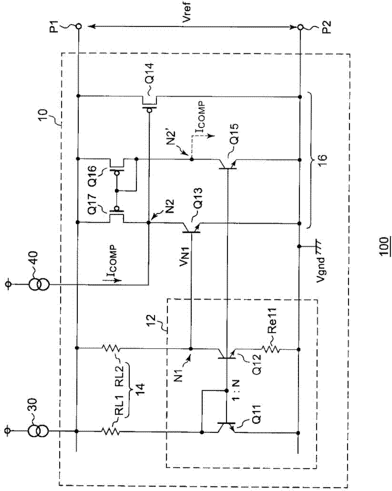
[0003] The BGR circuit described in Patent Document 1 can generate a stable reference voltage Vref with respect to power supply voltage and temperature, but the temperature coefficient δVref / δT is not completely zero, which may be insufficient depending on the application

Method used


Image

  • Current generation circuit and reference voltage circuit using the same
  • Current generation circuit and reference voltage circuit using the same
  • Current generation circuit and reference voltage circuit using the same

Examples


Embodiment Construction

[0045] Hereinafter, the present invention will be described based on preferred embodiments with reference to the drawings. The same or equivalent structural elements, members, and processes shown in the respective drawings are assigned the same reference numerals, and correspondingly repeated descriptions are omitted. In addition, the embodiment is not to limit the invention but to illustrate, and all the features described in the embodiment or combinations thereof are not necessarily essential features or combinations of the invention.

[0046] In this specification, the so-called "state where member A and member B are connected" includes not only the case where member A and member B are physically and directly connected, but also other members through which member A and member B do not affect the electrical connection state. The case of indirect connection.

[0047] Similarly, "a state in which member C is installed between member A and member B" includes, in addition to th...


PUM


Abstract

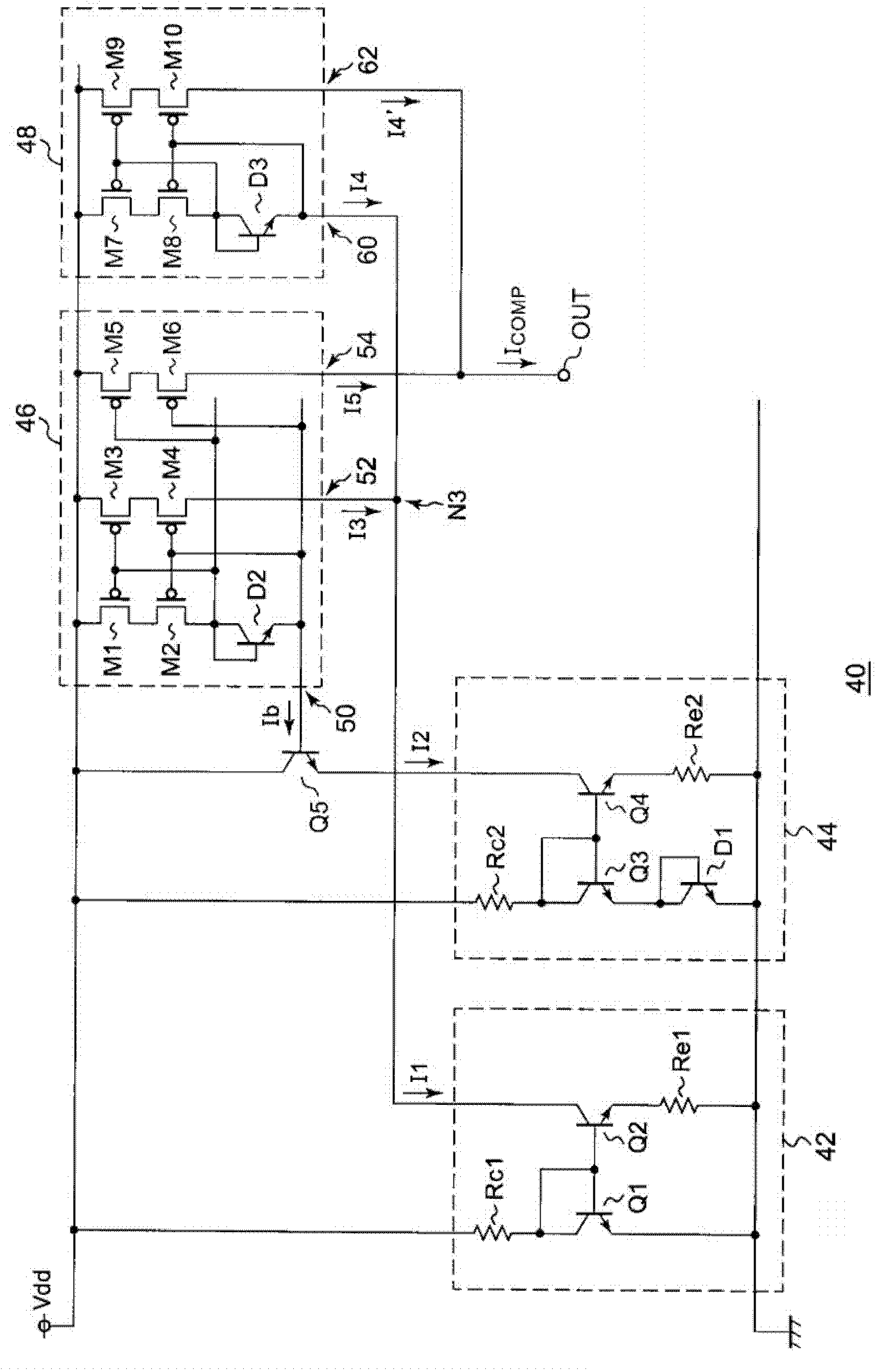
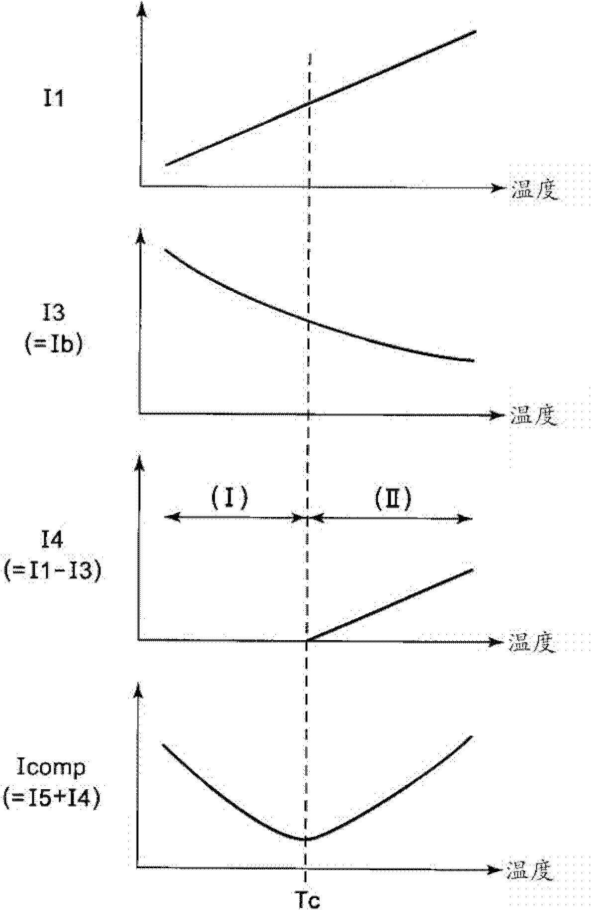
A current generating circuit may include a first current source configured to generate a first current having positive temperature characteristics; a second current source configured to generate a second current; a compensation transistor configured as an NPN bipolar transistor, and arranged such that the second current flows through from its collector and its emitter; and a first current mirror circuit configured to multiply a base current of the compensation transistor by a first coefficient so as to generate a third current. The current generating circuit may be configured to output a fourth current that is proportional to the difference between the first current and the third current.

Description

technical field [0001] The present invention relates to current generating circuits. Background technique [0002] In semiconductor integrated circuits, a band gap reference voltage circuit (also called a band gap reference (BGR) circuit (band gap reference circuit)) is used for the purpose of generating a constant voltage regardless of power supply voltage fluctuations or temperature fluctuations. Patent Document 1 discloses an example of a BGR circuit. [0003] The BGR circuit described in Patent Document 1 can generate a stable reference voltage Vref with respect to power supply voltage and temperature, but the temperature coefficient δVref / δT is not completely zero, which may be insufficient depending on the application. [0004] [Prior art literature] [0005] [Patent Document] [0006] [Patent Document 1] JP-A-5-088767 [0007] [Non-Patent Document 1] PAUL R.GRAY, PAUL J.HURST, STEPHEN H.LEWIS, ROBERT G.MEYER, ANALYSIS AND DESING OF ANALOG INTEGRATED CIRCUIT 4th Ed...

Claims


Application Information

Patent Timeline
Patent Type & Authority Patents(China)
IPC IPC(8): G05F3/26
CPCG05F3/30G05F3/26G05F3/225G05F3/267
Inventor 菊池弘基
Owner ROHM CO LTD
Learn More