Transverse magnetic flux linear reluctance motor with offset permanent magnet
A technology of transverse magnetic flux and permanent magnet bias, applied in the direction of electrical components, electromechanical devices, electric components, etc., can solve the problems of reduced reliability and safety and high cost of motors, and achieve high reliability and safety with low cost , cost reduction effect
- Summary
- Abstract
- Description
- Claims
- Application Information
AI Technical Summary
Problems solved by technology
Method used
Image
Examples
specific Embodiment approach 1
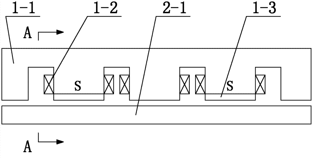
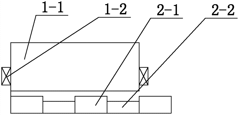
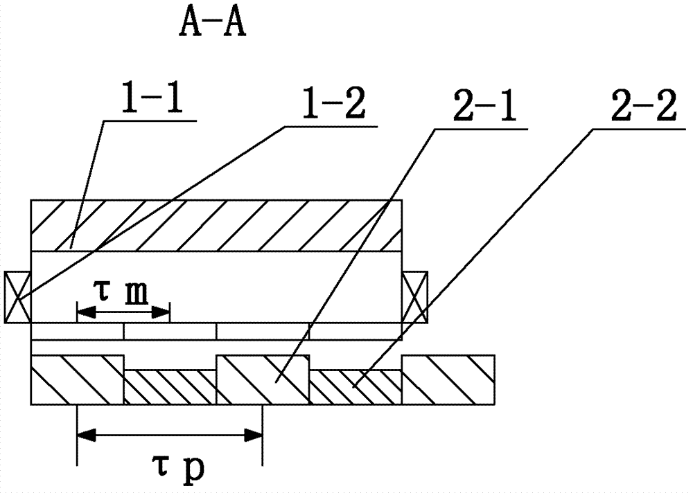
[0066] Specific implementation mode one: the following combination Figure 1 to Figure 3 This embodiment is described. The permanent magnet bias type transverse flux linear reluctance motor described in this embodiment includes a primary and a secondary, an air gap between the primary and the secondary, and the primary includes a plurality of phase armature units, each A phase armature unit is composed of a unit armature core 1-1, a phase unit armature winding 1-2 and a phase unit permanent magnet 1-3,
[0067] The unit armature core 1-1 is in the shape of a flat plate, and 2n through slots are evenly opened on the surface of the air gap side of the unit armature core 1-1 to form a tooth groove structure, and the slotting directions of the 2n through slots are all parallel to the motor direction of motion, n is a natural number greater than 1,
[0068] A coil is wound on the 2nd, 3rd, 4th, ... and 2n teeth of the unit armature core 1-1, and the winding directions of the coils...
specific Embodiment approach 2
[0072] Specific implementation mode two: the following combination Figure 4 to Figure 6 This embodiment is described. The permanent magnet bias type transverse flux linear reluctance motor described in this embodiment includes a primary and a secondary, an air gap between the primary and the secondary, and the primary includes a plurality of phase armature units, each A phase armature unit is composed of a unit armature core 1-1, a phase unit armature winding 1-2 and a phase unit permanent magnet 1-3,
[0073] The unit armature core 1-1 is in the shape of a flat plate, and m slots are evenly opened on the surface of the air gap side of the unit armature core 1-1 to form a cog structure, and the slotting directions of the m slots are all parallel to the motor direction of motion, m is a natural number greater than 1,
[0074] A coil is wound on the 2nd, 3rd, 4th, ... and the m teeth of the unit armature core 1-1, and the winding direction of the coil on every two adjacent tee...
specific Embodiment approach 3
[0078] Specific implementation mode three: the following combination Figure 7 to Figure 9 Describe this embodiment, this embodiment is a further description of Embodiment 2, the surface of the first and m+1th teeth of the unit armature core 1-1 of each phase armature unit in this embodiment are uniform There are phase unit permanent magnets 1-3 pasted.
[0079] The difference between this embodiment and the second embodiment is that phase unit permanent magnets 1-3 are pasted on the surfaces of the two teeth at both ends of the unit armature core 1-1.
PUM
 Abstract
Description
Claims
Application Information
 - R&D
- Intellectual Property
- Life Sciences
- Materials
- Tech Scout
- Unparalleled Data Quality
- Higher Quality Content
- 60% Fewer Hallucinations
Browse by: Latest US Patents, China's latest patents, Technical Efficacy Thesaurus, Application Domain, Technology Topic, Popular Technical Reports.
© 2025 PatSnap. All rights reserved.Legal|Privacy policy|Modern Slavery Act Transparency Statement|Sitemap|About US| Contact US: help@patsnap.com


