Isolation switch adjustment transformer band superposition rectification output circuit

A technology for adjusting transformers and isolating switches, which is applied in the direction of irreversible AC power input conversion to DC power output, conversion equipment with intermediate conversion to AC, and high-efficiency power electronic conversion. Jumping and other issues, to achieve the effect of light weight, small size, reliability and stability

Active Publication Date: 2011-12-28
SHAANXI HUAJING MICRO ELECTRONICS CO LTD
View PDF1 Cites 3 Cited by
  • Summary
  • Abstract
  • Description
  • Claims
  • Application Information

AI Technical Summary

Problems solved by technology

As a result, at the moment of opening and closing, the pulse width changes drastically, forming an output voltage jump
[0014] In addition, the switch structure is complex and bulky, which is not conducive to assembly into a miniature DC / DC converter, which is also a disadvantage

Method used


Image

  • Isolation switch adjustment transformer band superposition rectification output circuit
  • Isolation switch adjustment transformer band superposition rectification output circuit
  • Isolation switch adjustment transformer band superposition rectification output circuit

Examples


Embodiment Construction

[0039] The invention will be further described below through the embodiments and in conjunction with the accompanying drawings.

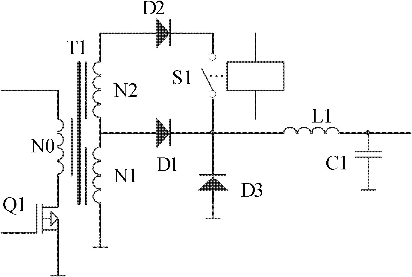
[0040] See attached image 3 .

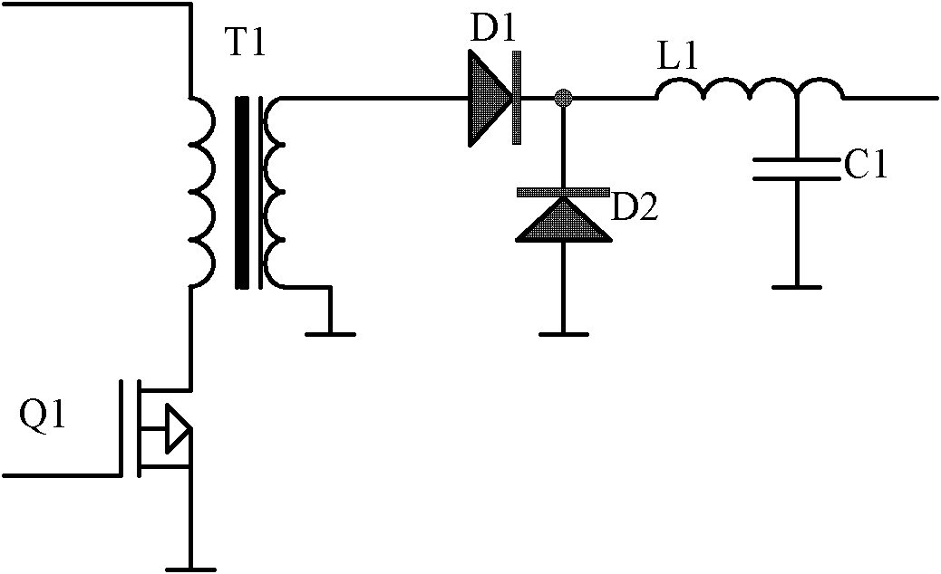
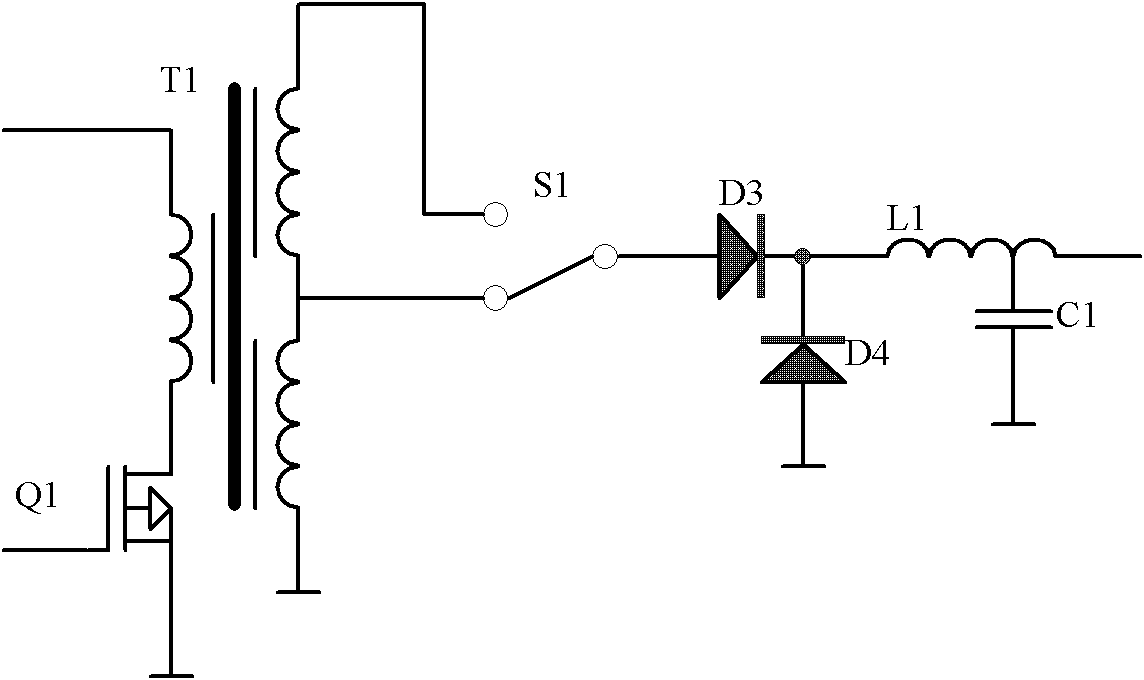
[0041] This solution utilizes the unidirectional conduction characteristic of the rectifier diode D1 to endow the D1 diode with new functions. The backup winding of the transformer and the backup diode D2 connected in series form a parallel connection with the D1 diode through a switch S1 (such as an optical control isolating switch), and at the same time form a series connection with the basic winding of the transformer.

[0042] When necessary, for example, when the wide input voltage is transferred to the low-voltage range, the switch S1 is closed, the transformer backup winding N2 is superimposed in series with the original winding N1, and the output secondary winding becomes more, that is, the transformer turns ratio is changed, and the PWM of the DC / DC converter The modulated pulse width will fall back into a...


PUM


Abstract

The invention provides an isolating switch regulated transformer wave band superposing, rectifying and outputting circuit. The circuit is endowed with a new function by using the unidirectional switching-on characteristic of a rectifying diode of a direct current/direct current (DC/DC) converter, and a standby winding of a transformer and a standby diode connected in series with the standby winding are connected in parallel with the original rectifying diode through an isolating switch and connected in series with a basic winding of the transformer simultaneously, so that the output turn number can be changed when necessary, and the DC/DC converter can meet the requirement of a wider input voltage range. By the circuit, the problem that the DC/DC converter with a wide input range has low efficiency, reliability and stability at the present stage is solved, and a jump-free, high-efficiency and reliable isolating switch regulated transformer segmented rectifying and outputting technicalscheme is provided.

Description

technical field [0001] The present invention relates to analog electronics DC / DC converter technology. Background technique [0002] As the application range of DC / DC converters becomes wider and wider, the requirements for the application range of DC / DC converters become wider and wider. DC / DC converters with a wide input voltage range are more and more popular with market users. [0003] The traditional PWM (Pulse Width Modulation) DC / DC converter uses a transformer with a fixed turn ratio. The applicable input voltage range is generally double the voltage, such as 9V~18V, or 18V~36V, or 36V~72V, and so on. . For its converter and rectifier circuit, see the attached figure 1 . [0004] A DC / DC converter with a "wide input voltage range" requires a wider input voltage range, such as 9V to 36V, or 9V to 72V, and so on. In this way, due to the limitation of the pulse width modulation range of the traditional PWM type DC / DC converter, in the limit state (when the input vo...

Claims


Application Information

Patent Timeline
Patent Type & Authority Applications(China)
IPC IPC(8): H02M7/30H02M3/34
CPCY02B70/16Y02B70/10
Inventor 胡元毛国华姜耀升
Owner SHAANXI HUAJING MICRO ELECTRONICS CO LTD
Why Eureka
Try Eureka