Image compression device, image compression method, and vehicle-mounted image recording device

A technology of image compression and surrounding images, which is applied in image communication, optical observation devices, vehicle parts, etc., can solve problems such as inability to respond, failure to respond, and accidents prone to occur

Inactive Publication Date: 2011-12-28
PANASONIC CORP
View PDF2 Cites 13 Cited by
  • Summary
  • Abstract
  • Description
  • Claims
  • Application Information

AI Technical Summary

Problems solved by technology

It cannot cope with situations where accidents such as sudden start, sudden stop, and sharp turn may occur
In addition, although the image quality control of accident-prone places is carried out using the position information of the own vehicle, it cannot respond to accident-prone situations such as driving on unfamiliar roads

Method used


Image

  • Image compression device, image compression method, and vehicle-mounted image recording device
  • Image compression device, image compression method, and vehicle-mounted image recording device
  • Image compression device, image compression method, and vehicle-mounted image recording device

Examples


no. 1 approach

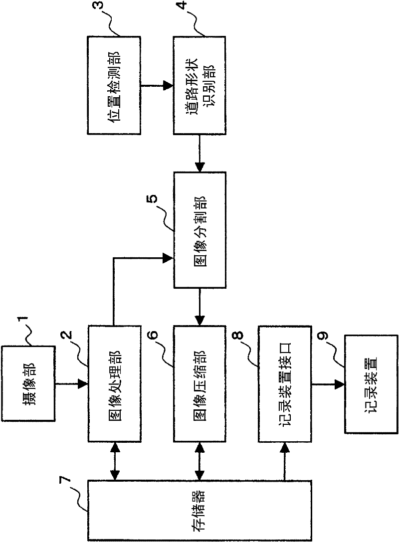
[0139] figure 1 It is a block diagram showing the structure of the in-vehicle image recording apparatus in the first embodiment of the present invention.

[0140] The in-vehicle image recording device includes an imaging unit 1 , an image processing unit 2 , a position detection unit 3 , a road shape recognition unit 4 , an image division unit 5 , an image compression unit 6 , a memory 7 , a recording device interface 8 , and a recording device 9 .

[0141] The imaging unit 1 captures an image of the surroundings of the traveling own vehicle. The image processing unit 2 performs image processing on the surrounding image data output from the imaging unit 1 . The position detection unit 3 detects the position of the running vehicle. The road shape recognition unit 4 prestores map information including road shapes at various points, and recognizes the road shape detected by the position detection unit 3 by comparing it with the map information in which the position of the vehic...

no. 2 approach

[0172] Figure 17 It is a block diagram showing the structure of the in-vehicle image recording apparatus in the second embodiment of the present invention. exist Figure 17 , the same as that of the first embodiment figure 1 The same symbols in represent the same structural elements. In the present embodiment, a vehicle speed detection unit 10 for detecting the traveling speed of the own vehicle is further added to the first embodiment. The image dividing unit 5 is configured to divide surrounding image data based on the recognition result of the road shape recognition unit 4 and the detection result of the vehicle speed detection unit 10 , and to assign a data compression rate to each divided area individually. The traveling speed of the own vehicle detected by the vehicle speed detection unit 10 is sent to the image dividing unit 5 and used for the change of the size change unit when the size of the divided area is changed. The faster the vehicle speed is, the faster th...

no. 3 approach

[0175] The incidence of accidents is not only related to the shape of the road, but also to the driving state of the vehicle. The present embodiment focuses on the traveling speed of the host vehicle in the traveling state of the host vehicle. For example, when the vehicle is driven at a slow speed, the possibility of an accident is low, and on the contrary, when the vehicle is driven at a high speed, the possibility of an accident is high. Therefore, it is possible to record with high image quality when the vehicle is traveling at a high speed.

[0176] Figure 20It is a block diagram showing the configuration of the vehicle-mounted image recording device in the third embodiment of the present invention. The vehicle-mounted image recording device has: an imaging unit 1 that captures a surrounding image of the vehicle; an image processing unit 2 that performs image processing on the surrounding image data output by the imaging unit 1; a vehicle speed detection unit 10 that d...


PUM


Abstract

A road shape recognition device checks a position of a currently travelling vehicle detected by a position detection device with map information so that a road shape at each travelling spot of the currently travelling vehicle is recognized. An image division device divides a display screen of surrounding image data of the currently travelling vehicle into a plurality of divided regions depending on the road shape and sets a data compression rate suitable for the road shape in each of the plurality of divided regions. An image compression device compresses the surrounding image data in each of the plurality of divided regions into codes based on the data compression rate set for each of the divided regions.

Description

technical field [0001] The invention relates to an image compression device, an image compression method and an in-vehicle image recording device in a vehicle-mounted camera, in particular to adaptively control the data compression rate and frame rate of an image according to changes in road conditions and driving conditions, so as to solve the problem of image quality A technology that balances the contradiction between level and recording time. Background technique [0002] In recent years, drive recorders mounted on vehicles can record images at the moment or before and after a traffic accident. Such a drive recorder, for example, is configured to temporarily store image information captured by a CCD camera and compressed in a random access memory at any time, and sensor information such as an acceleration sensor, etc., so that if an accident occurs, the sensor collides with the sensor. operation, the latest recorded information just before the collision is transferred f...

Claims


Application Information

Patent Timeline
Patent Type & Authority Applications(China)
IPC IPC(8): H04N7/26B60R1/00B62D41/00H04N5/92H04N7/18G07C5/00H04N5/765H04N19/00H04N19/115H04N19/132H04N19/134H04N19/167H04N19/172H04N19/174H04N19/189H04N19/20
CPCH04N9/8205H04N19/0006G06K9/00798H04N19/00751H04N19/0026H04N19/00127H04N5/772H04N9/8042H04N19/00266H04N19/172H04N19/115H04N19/132H04N19/17H04N19/587G06V20/588
Inventor 野津拓马小川雅裕
Owner PANASONIC CORP
Why Eureka
Try Eureka