Piston type internal combustion engine

An internal combustion engine, piston type technology, applied in the direction of internal combustion piston engine, combustion engine, mechanical equipment, etc., can solve the problems of difficulty in manufacturing and maintenance, uneven force on the crankshaft, low transmission efficiency, etc., to avoid power loss and cylinder wear, Simple manufacturing and maintenance, compact structure

Inactive Publication Date: 2013-01-23
贵州创能科技有限公司
View PDF7 Cites 0 Cited by
  • Summary
  • Abstract
  • Description
  • Claims
  • Application Information

AI Technical Summary

Problems solved by technology

[0012] 1. The existing reciprocating piston internal combustion engine has the problems of low transmission efficiency, easy wear of the cylinder and uneven stress on the crankshaft
[0013] 2. Existing rotary engines have the problems of incomplete exhaust gas emission, too small torque, easy wear of the seal, only ignition type, and difficulties in manufacture and maintenance.

Method used


Image

  • Piston type internal combustion engine
  • Piston type internal combustion engine
  • Piston type internal combustion engine

Examples


Embodiment 1

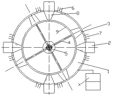
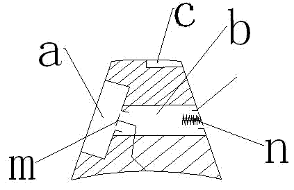
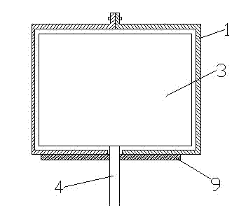
[0040] Such as figure 1 , the cylinder 1 is an annular cylinder, and four sliders 2 are evenly arranged on the cylinder 1 along the circumference, and the cylinder 1 is divided into 4 working rooms, and each working room is provided with a piston 3, an intake valve 6 and an exhaust valve 7, and the cylinder 1. It is formed by merging two halves of the cylinder wall. The outer edge of the outer circle is sealed and fixed with bolts. There is an annular seam on the inner circle of the cylinder wall of cylinder 1, and a sealing device 9 is set at the annular seam; piston connecting rod 4 It is connected to the piston 3 through the gap of the annular gap, and the other end is connected to the main power shaft 5 located in the center of the ring; the slider 2 is provided with an oil injection ignition device 8; the top of the piston 3 has an exhaust groove c, the length of which is the length of the top There is a combustion chamber a on the left side, a compressed gas storage cha...

Embodiment 2

[0054] Embodiment 2 adopts mechanical control system, such as Figure 5 and Figure 6 , the cylinder 1 is an annular cylinder, and four sliders 2 are evenly arranged on the cylinder 1 along the circumference, and the cylinder 1 is divided into 4 working rooms, and each working room is provided with a piston 3, an intake valve 6 and an exhaust valve 7, and the cylinder 1. It is formed by merging two halves of the cylinder wall. The outer edge of the outer circle is sealed and fixed with bolts. There is an annular seam on the inner circle of the cylinder wall of cylinder 1, and a sealing device 9 is set at the annular seam; piston connecting rod 4 It is connected to the piston 3 through the gap of the annular seam, and the other end is connected to the main power shaft 5 located in the center of the ring; the fuel injection and ignition device 8 is arranged on the slider 2; an exhaust groove c is opened on the top of the piston 3, and there is a The combustion chamber a has a c...


PUM


Abstract

The invention discloses a piston type internal combustion engine. An air cylinder (1) of the piston type internal combustion engine is an annular air cylinder; more than four sliding blocks (2) are uniformly arranged on the air cylinder (1) along the circumference so as to divide the air cylinder (1) into more than four working chambers; each working chamber is provided with an air inlet valve (6), an air exhaust valve (7) and a piston (3); one end of a piston connection rod (4) is connected with the piston (3) and the other end of the piston connection rod (4) is connected with a main power shaft (5) in an annular center; oil spraying ignition devices (8) are arranged on the sliding blocks (2); and the work of the air inlet valves (6), the air exhaust valves (7) and the sliding blocks (2) is controlled by a control system. The piston type internal combustion engine has a simple structure and is easy to manufacture; and by the piston type internal combustion engine, the problems that power loss is high, the air cylinder of the conventional reciprocating piston type internal combustion engine is easy to abrade and the stress on a crank shaft is unbalanced in the conventional reciprocating piston type internal combustion engine and the problems that a sealing sheet of a rotor engine is easy to abrade, waste gas cannot be emitted thoroughly, the torque is too small, only one spark ignition mode can be adopted and a rotor engine is hard to manufacture and maintain in the rotor engine are solved.

Description

technical field [0001] The invention relates to the technical field of an internal combustion engine structure. Background technique [0002] The internal combustion engine is an energy conversion device that converts the chemical energy of gasoline, diesel, natural gas and other substances into thermal energy through combustion in the cylinder, and the thermal energy is converted into mechanical energy through expansion to perform work externally. Reciprocating piston internal combustion engines are generally used in commercial vehicles at present. [0003] After the reciprocating piston internal combustion engine converts chemical energy into thermal energy in the cylinder, the thermal energy expands and drives the piston to move, thereby converting the thermal energy into mechanical energy, and then converts the energy into the torque of the crankshaft through the crank-link mechanism to perform work externally. [0004] The crank connecting rod mechanism is the main wor...

Claims


Application Information

Patent Timeline
Patent Type & Authority Patents(China)
IPC IPC(8): F02B55/08F02B55/02F02B53/06F02B55/16
CPCY02T10/17Y02T10/12
Inventor 郭革委
Owner 贵州创能科技有限公司
Why Eureka
Try Eureka