
Exhaust fan

A technology of exhaust fans and fan casings, which is applied to the components of pumping devices for elastic fluids, non-variable displacement pumps, machines/engines, etc. big problem

Inactive Publication Date: 2012-01-04
SHENZHEN ACTO DIGITAL VIDEO TECH
View PDF7 Cites 2 Cited by
  • Summary
  • Abstract
  • Description
  • Claims
  • Application Information

AI Technical Summary

Problems solved by technology

[0003] However, the traditional exhaust fan only has a relatively large air suction volume near the blade frame, and the air suction volume at the center is not enough. When cooling the components, the exhaust fan has a small exhaust air volume, which cannot effectively cool the components, and the cooling efficiency is not high. , which greatly limits the use of the exhaust fan

Method used


Image

  • Exhaust fan
  • Exhaust fan
  • Exhaust fan

Examples


Embodiment Construction

[0018] The specific implementation manners of the present invention will be described in detail below in conjunction with the accompanying drawings.

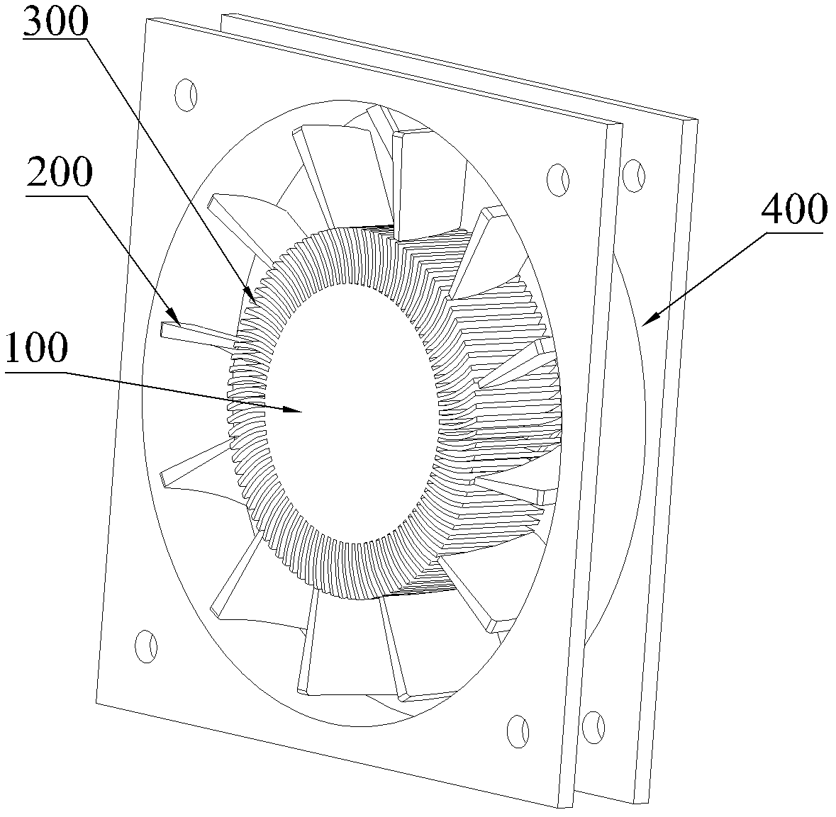
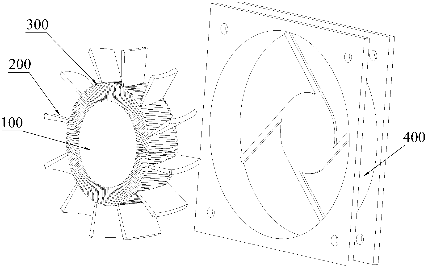
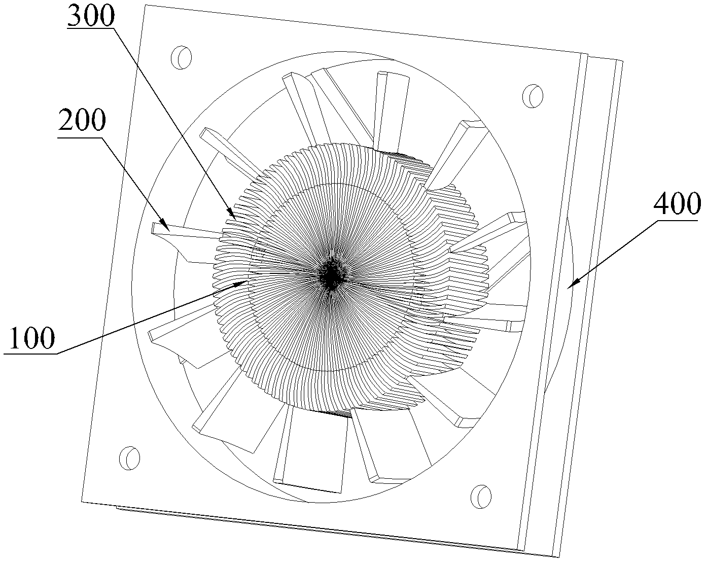
[0019] figure 1 It is a structural schematic diagram of an exhaust fan in an embodiment. figure 2 yes figure 1 An exploded view of the exhaust fan shown. The exhaust fan includes a shaft sleeve 100 , a first fan blade 200 , a second fan blade 300 and a fan case 400 .

[0020] The shaft sleeve 100 is used to be connected with the motor and driven to rotate by the motor.

[0021] There are multiple first fan blades 200 , all of which are arranged on the outer peripheral surface of the shaft sleeve 100 along the radial direction of the shaft sleeve 100 . The first fan blade 200 is an axial flow fan blade, which is used for sucking in air along the axial direction of the exhaust fan and blowing the air out along the axial direction of the exhaust fan to cool the components. In this embodiment, a plurality of first fan blades 2...


PUM


Abstract

The invention relates to an exhaust fan which comprises a shaft sleeve, a plurality of first blades and a plurality of second blades, wherein the first blades are axial-flow blades and all arranged on the peripheral surface of the shaft sleeve along the radial direction of the shaft sleeve; and the second blades are eddy-flow blades and are distributed among the plurality of first blades and arranged on the peripheral surface of the shaft sleeve along the radial direction of the shaft sleeve. According to the invention, the second blades are arranged in the first blade intervals and are arranged at the periphery of the shaft sleeve; and the second blades axially extract cold air from the outside and radially blow the cold air to the first blade intervals, thereby increasing the air extraction in the center of the exhaust fan blades and the air amount in the first blade intervals, thus the air exhaust and wind pressure of the first blades are increased, the cooling efficiency of the exhaust fan is greatly improved, and the performance of the exhaust fan is enhanced.

Description

【Technical field】 [0001] The invention relates to a fan, in particular to an exhaust fan. 【Background technique】 [0002] Exhaust fans are widely used today, ranging from aircraft, ships, to mini projectors. [0003] However, the traditional exhaust fan only has a relatively large air suction volume near the blade frame, and the air suction volume at the center is not enough. When cooling the components, the exhaust fan has a small exhaust air volume, which cannot effectively cool the components, and the cooling efficiency is not high. , which greatly limits the use of exhaust fans. 【Content of invention】 [0004] In view of this, it is necessary to provide an exhaust fan with high cooling efficiency. [0005] An exhaust fan, comprising a shaft sleeve, a first fan blade and a second fan blade; the first fan blade is an axial flow fan blade, and there are a plurality of first fan blades, all along the diameter of the shaft sleeve The second fan blade is arranged on the o...

Claims


Application Information

Patent Timeline
IPC IPC(8): F04D29/26
Inventor 曾万军
Owner SHENZHEN ACTO DIGITAL VIDEO TECH
Learn More