

Total heat exchanger
A technology of heat exchanger and heat exchange cavity, which is applied in the direction of household heating, household heating, heating method, etc., can solve the problems of short exchange time between outdoor air and indoor air, and the heat exchange effect is not obvious, so as to save power consumption. , Simple design, low noise effect
- Summary
- Abstract
- Description
- Claims
- Application Information
AI Technical Summary
Problems solved by technology
Method used
Image

Examples
no. 1 example
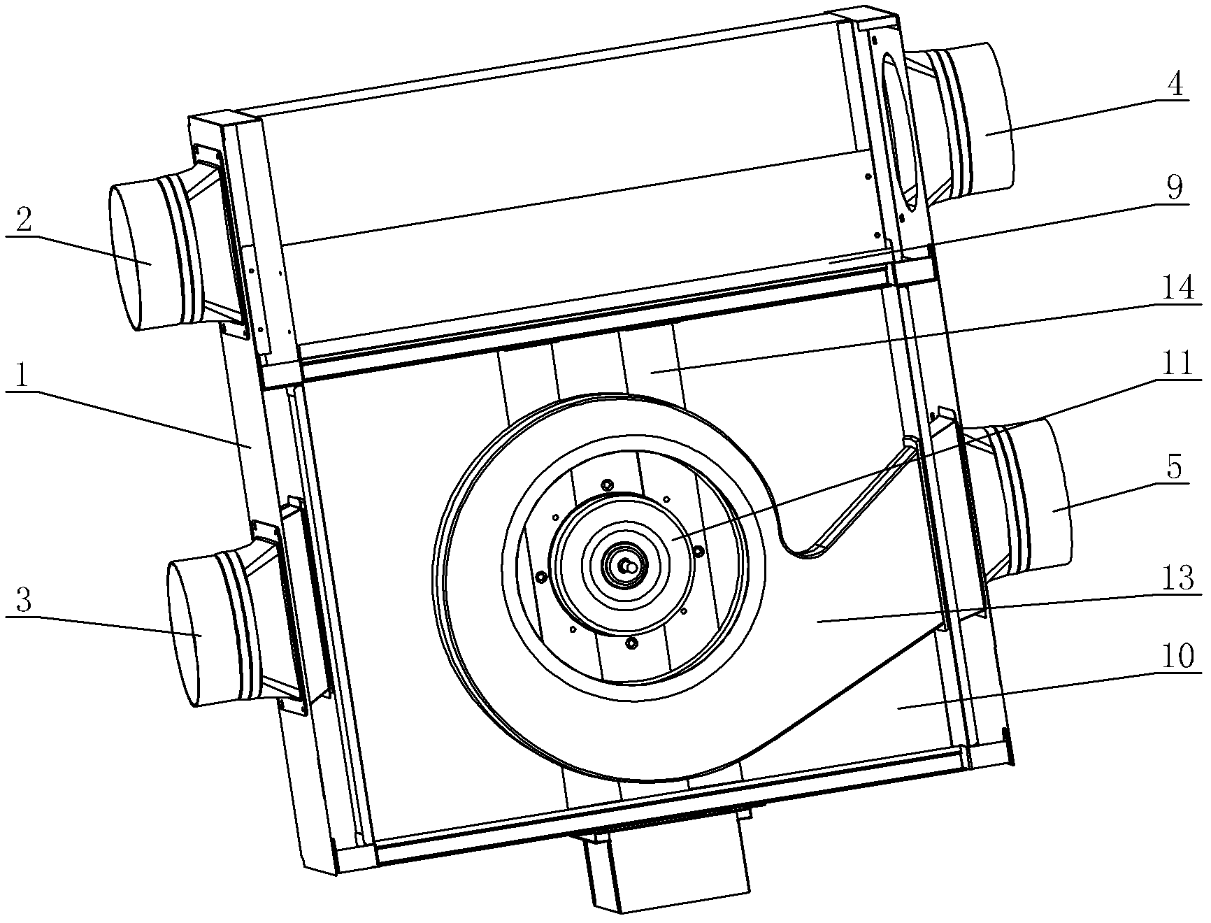
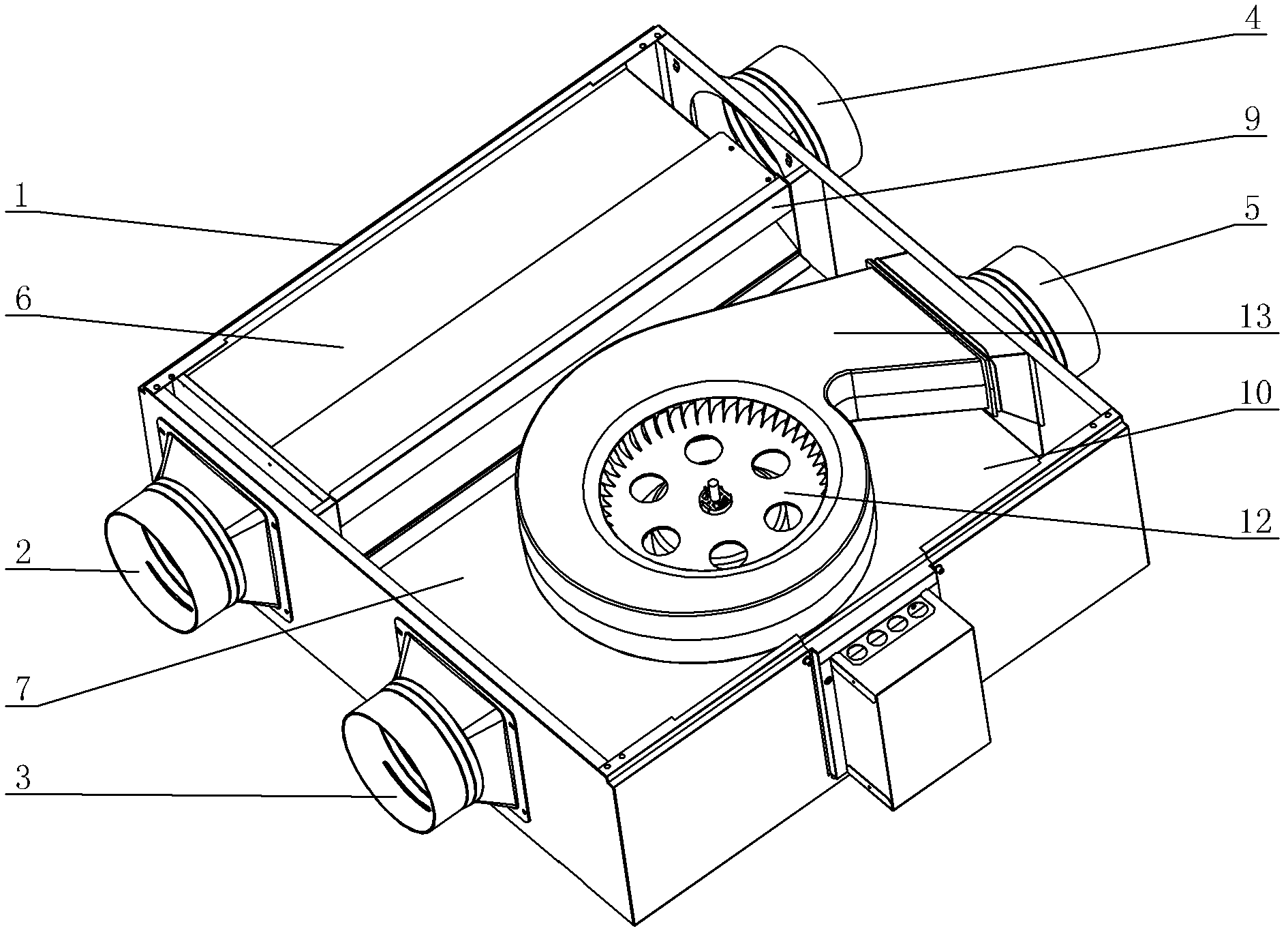
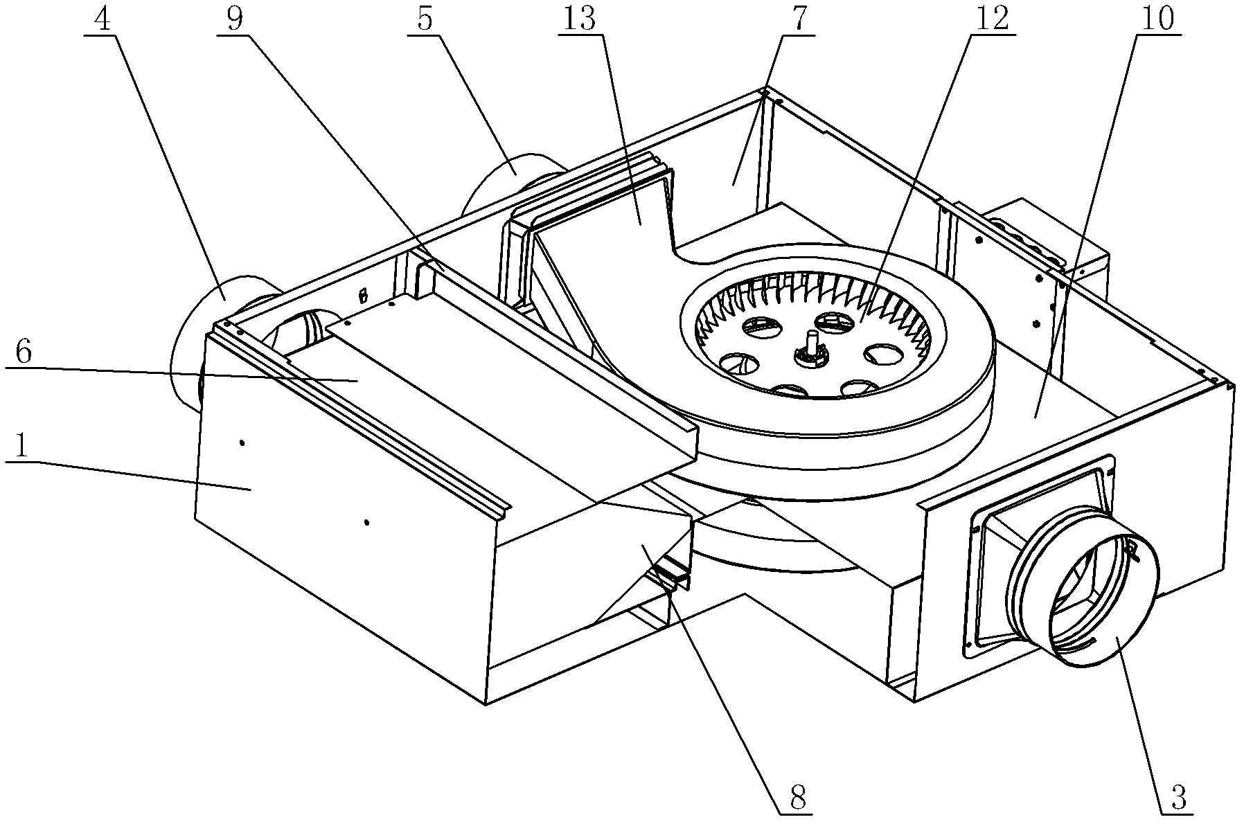
[0029] see Figure 1-Figure 8 , the total heat exchanger includes an indoor air inlet 2 and an indoor fresh air exhaust port 3 arranged on the front side of the casing 1, and an outdoor fresh air inlet 4 and an outdoor air exhaust outlet arranged on the rear side of the casing 1 corresponding to each other. The air port 5, the casing 1 is provided with a partition 9 corresponding to two air inlets and two exhaust ports, and divides the inside of the casing 1 into left and right heat exchange chambers 6 and exhaust chambers 7.
[0030] The heat exchange chamber 6 communicates with the indoor air inlet 2 and the outdoor fresh air inlet 4 respectively. A heat exchange core 8 is arranged inside the heat exchange chamber 6. The heat exchange core 8 is a group, and its size is the same as that of the heat exchange chamber. Size matches. The side of the heat exchange core 8 corresponding to the exhaust chamber 7 is provided with an acute-angle air outlet surface. The above shape can...
no. 2 example
[0034] see Figure 9-Figure 14 , The main difference between this total heat exchanger and the first embodiment is that the heat exchange cores 8 are in three groups, and the size of each group is about one-third of the size of the heat exchange cavity. The side of the heat exchange core 8 corresponding to the exhaust chamber 7 is provided with a vertical air outlet surface. According to actual needs, it can also be designed as an inclined air outlet surface, or an arc-shaped air outlet surface, or an air outlet surface of other shapes. On the other hand, its main purpose is to increase the air outlet area of the heat exchange core 8, which can not only increase the air outlet volume, but also reduce the operating noise of the device.
[0035] The separators 9 of the present embodiment are divided into four layers from top to bottom, wherein the separators 9 of the upper and lower layers are respectively connected to the top and bottom of the heat exchange core 8, and the se...
PUM
 Abstract
Description
Claims
Application Information