Overvoltage protection device and preparation method thereof
A protector and overvoltage technology, which is applied in the direction of emergency protection circuit devices, emergency protection circuit devices, electrical components, etc. for limiting overcurrent/overvoltage, and can solve the problem of inability to protect electrical equipment and effectively limit phase and Phase overvoltage, lightning arrester does not have the function of arc suppression, etc., to achieve the effect of protection safety
- Summary
- Abstract
- Description
- Claims
- Application Information
AI Technical Summary
Problems solved by technology
Method used
Image
Examples
Embodiment 1
[0030] Example 1: (1) Dry the zinc oxide resistors at a temperature of 80°C and a drying time of 10 hours;
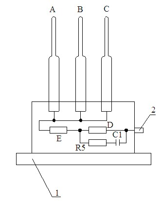
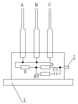
[0031] (2) Configure the first resistor piece A, the second resistor piece B, the third resistor piece C and the discharge device: use a dried 42x17kV zinc oxide resistor and two 42x30kV aluminum electrodes in series. The first resistor piece A is formed by winding it with dipped glass fiber yarn without weft tape. Among them, a 42x17kV zinc oxide resistor piece is connected in series between two pieces of 42x30kV aluminum electrode; the second resistor piece B and the first The configuration process of the three resistors C is exactly the same as that of the first resistor A; a 9.1kV zinc oxide resistor is connected in series with an 11.3kV discharge gap, and a fifth resistor R5 is connected in parallel at both ends of the discharge gap The series circuit formed by the capacitor C1 is configured as a discharge device;
[0032] (3) Drying and finalizing the configured fir...
Embodiment 2
[0037] Example 2: (1) Dry the zinc oxide resistor strip at a temperature of 100°C and a drying time of 9 hours;
[0038] (2) Configure the first resistor piece A, the second resistor piece B, the third resistor piece C and the discharge device: use a dried 42x17kV zinc oxide resistor piece in series with two 42x30kV aluminum electrodes The first resistor piece A is formed by winding the dipped glass fiber yarn without weft tape, in which a 42x17kV zinc oxide resistor piece is connected in series between two pieces of 42x30kV aluminum electrode; the second resistor piece B and the third The configuration process of resistor chip C is exactly the same as that of the first resistor chip A; a 9.1kV zinc oxide resistor is connected in series with an 11.4kV discharge gap, and a fifth resistor R5 is connected in parallel at both ends of the discharge gap. The series circuit formed by the capacitor C1 is configured as a discharge device;
[0039] (3) Drying and finalizing the configured...
Embodiment 3
[0044] Embodiment 3: (1) Dry the zinc oxide resistor strip at a drying temperature of 120°C and a drying time of 8 hours;
[0045] (2) Configure the first resistor piece A, the second resistor piece B, the third resistor piece C and the discharge device: use a dried 42x17kV zinc oxide resistor in series with two 42x30kV aluminum electrodes The first resistor piece A is formed by winding the dipped glass fiber yarn without weft tape, in which the ?42x17kV zinc oxide resistor piece is connected in series between two ?42x30kV aluminum electrodes; the second resistor piece B and the third The configuration process of resistor chip C is exactly the same as that of the first resistor chip A; one 9.1kV zinc oxide resistor is connected in series with a 11.5kV discharge gap, and a fifth resistor R5 is connected in parallel at both ends of the discharge gap. The series circuit formed by the capacitor C1 configures the discharge device;
[0046] (3) Drying and finalizing the configured fir...
PUM
 Abstract
Description
Claims
Application Information
 - R&D
- Intellectual Property
- Life Sciences
- Materials
- Tech Scout
- Unparalleled Data Quality
- Higher Quality Content
- 60% Fewer Hallucinations
Browse by: Latest US Patents, China's latest patents, Technical Efficacy Thesaurus, Application Domain, Technology Topic, Popular Technical Reports.
© 2025 PatSnap. All rights reserved.Legal|Privacy policy|Modern Slavery Act Transparency Statement|Sitemap|About US| Contact US: help@patsnap.com


