Feed line automation system

A feeder automation and feeder technology, which is applied in information technology support systems, electrical components, circuit devices, etc., can solve the problems of high communication reliability requirements, heavy burden on the main station, and slow down the processing speed of failures. And the effect of processing direct and fast, shortening the time of fault processing, reducing communication paralysis

Inactive Publication Date: 2012-01-04
STATE GRID ZHEJIANG NINGBO YINZHOU POWER SUPPLY LTD CO
View PDF4 Cites 28 Cited by
  • Summary
  • Abstract
  • Description
  • Claims
  • Application Information

AI Technical Summary

Problems solved by technology

[0003] The conventional implementation mode of feeder automation is the centralized control type, which requires a communication channel and a control master station. The communication system is the link between the master station system and the terminal equipment of the distribution network. When a fault occurs, the control master station receives the feeder terminal ( Feeder Terminal Unit (FTU) collects fault information, locates faults, and issues control commands. All operations are performed by the master station, so the burden on the master station is heavy, and the speed of processing faults slows down. At the same time, the FTU Upload information to the master station, the master station sends control information to the FTU, and the information needs to be transmitted back and forth between the master station and the FTU, which results in prolonged fault

Method used


Image

  • Feed line automation system
  • Feed line automation system
  • Feed line automation system

Examples


Embodiment 1

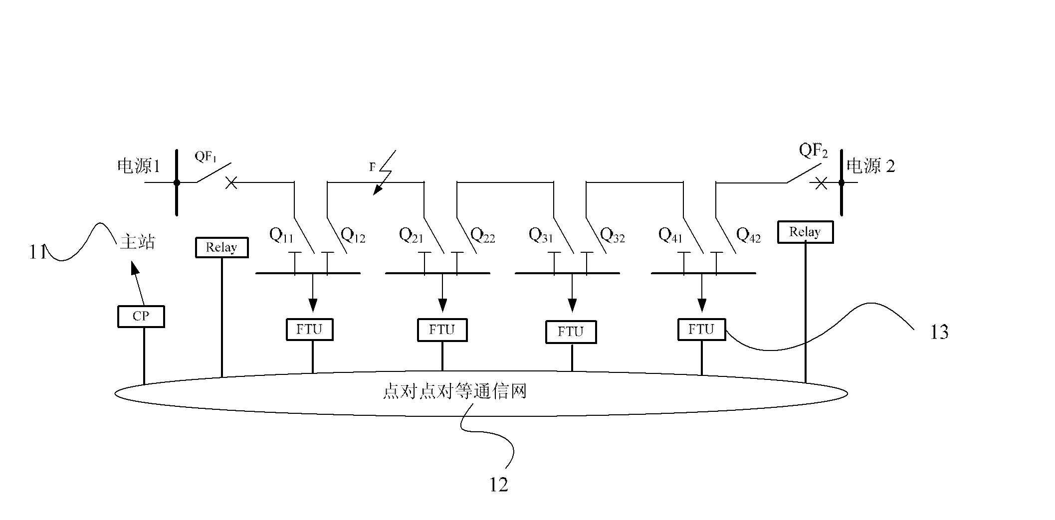
[0030] See figure 1 , the feeder automation system disclosed in the embodiment of the present invention includes a master station system 11 , a point-to-point peer-to-peer communication network 12 and a distribution automation terminal FTU 13 . The master station system 11 is connected to a communication processor (Communication Processor, CP), and the CP is connected to the point-to-point communication network 12; the FTU 13 is connected to the point-to-point communication network 12. The point-to-point peer-to-peer communication network 12 is used to realize peer-to-peer communication between adjacent FTUs 13, and the FTUs 13 are used to perform local fault location, fault isolation and power supply recovery of non-faulty sections, and the CP is used to forward the information of the FTU 13 to the main station 11 data, the data is provided to the staff of the master station as the time processing sequence soe information of the master station 11.

[0031] The system logic s...

Embodiment 2

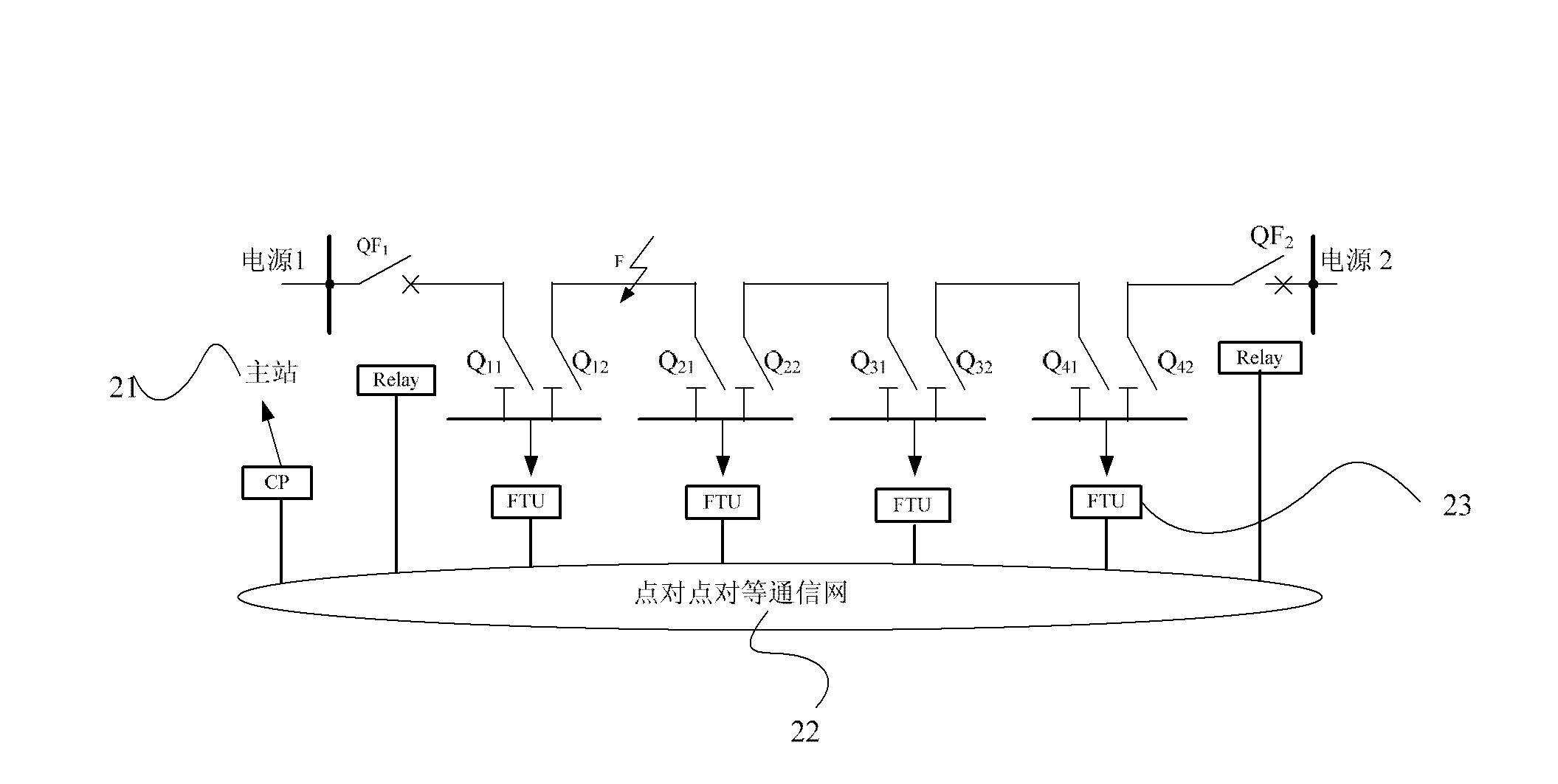
[0048] See figure 2 , The feeder automation system disclosed in this embodiment includes: a master station system 21 , a peer-to-peer network 22 and a distribution automation terminal FTU 23 . The master station system 21 is connected to a communication processor (Communication Processor, CP), and the CP is connected to the peer-to-peer network 22 ; the FTU 23 is connected to the peer-to-peer network 22 .

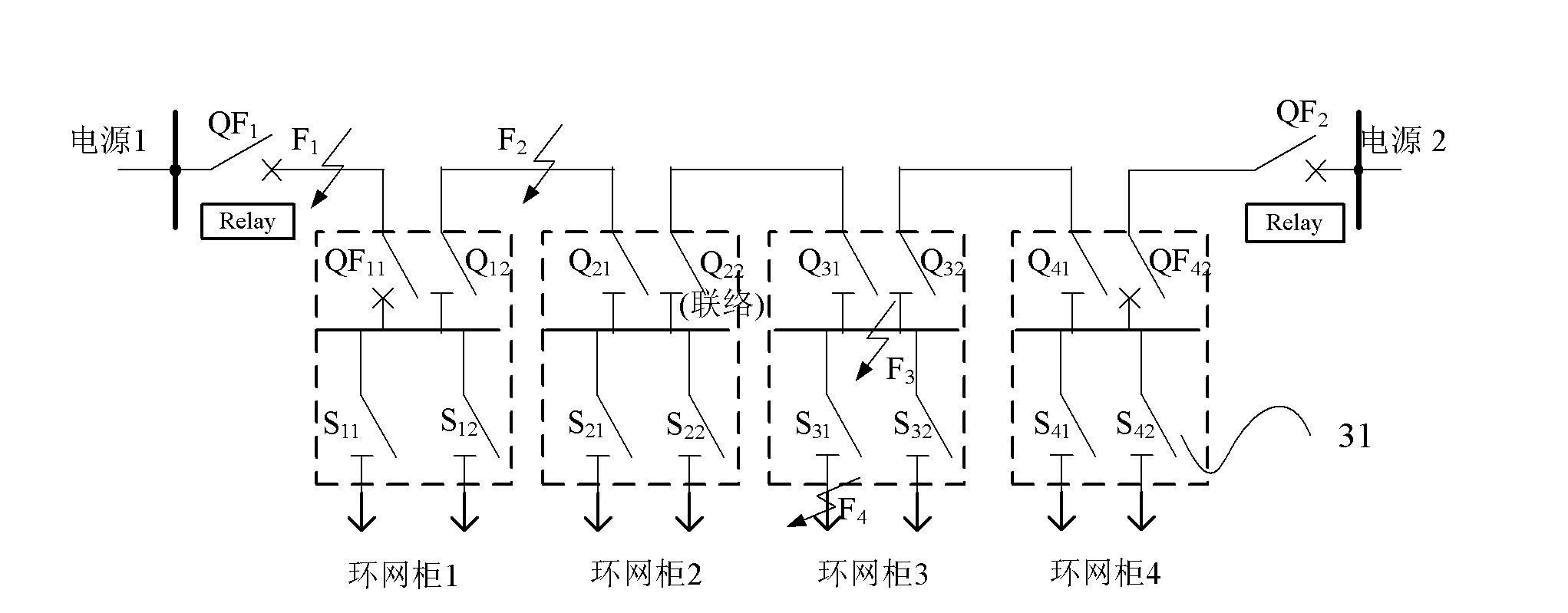
[0049] In the system disclosed in this embodiment, the point-to-point peer-to-peer communication network is an optical fiber industrial Ethernet; image 3As shown, the FTU22 is arranged in the ring main unit 31; the switch type of the ring main unit 31 is: the incoming line switch is a circuit breaker, and the outgoing line switch is a load switch. The bus bar of the ring main unit 31 is configured with a single-phase voltage transformer PT, and the incoming and outgoing lines of the ring main unit 31 are configured with a three-phase current transformer CT. Circuit brea...


PUM


Abstract

The invention discloses a feed line automation system which comprises a main station system, a point-to-point equity communication network and a distribution automation terminal FTU (Feeder Terminal Unit). The FTU connects to the point-to-point equity communication network. The main station system connects with a communication processor CP which connects to the point-to-point equity communication network. The point-to-point equity communication network is used for realizing direct communication between adjacent FTUs. The FTU is used for positioning a fault, isolating the fault and recovering power supply of a non fault section. The CP is used for forwarding FTU data to the main station. The main station receives the FTU data forwarded by the main station, and the data is provided to work personnel of the main station as time processing sequence soe information.

Description

technical field [0001] The invention relates to the technical field of power system automation, in particular to a feeder automation system. Background technique [0002] At present, in order to reduce the failure time of the medium-voltage power grid, the feeder automation has been widely valued by people. Feeder automation refers to the automation of feeder lines between substation outgoing lines and user equipment. It is used for user detection, data measurement and operation optimization under normal conditions, as well as fault detection, fault isolation, transfer and restoration of power supply control under accidental conditions. [0003] The conventional implementation mode of feeder automation is the centralized control type, which requires a communication channel and a control master station. The communication system is the link between the master station system and the terminal equipment of the distribution network. When a fault occurs, the control master station ...

Claims


Application Information

Patent Timeline
IPC IPC(8): H02J13/00H02H7/26
CPCY02E60/725Y04S10/20Y02E60/00
Inventor 胡杰王吉庆高颂九凌荣光李光军张彦郑坤力李金海张惠芳胡余坚黄继明邱剑斌
Owner STATE GRID ZHEJIANG NINGBO YINZHOU POWER SUPPLY LTD CO
Why Eureka
Try Eureka