Permanent magnet biased bearingless switched reluctance motor

A switched reluctance motor and permanent magnet bias technology, which is applied in the direction of electrical components, electromechanical devices, torque ripple control, etc., can solve the problems of increased levitation force, nonlinearity, and complex magnetic field distribution of the motor, so as to reduce the levitation work Consumption, improve the effect of motor efficiency

Inactive Publication Date: 2012-01-04
南京埃克锐特机电科技有限公司
View PDF5 Cites 52 Cited by
  • Summary
  • Abstract
  • Description
  • Claims
  • Application Information

AI Technical Summary

Problems solved by technology

The existing bearingless switched reluctance motor torque winding and suspension winding are installed on the same stator teeth, resulting in strong coupling between the main winding and suspension winding, resulting in complex magnetic field distribution inside the motor, and bearingless switched reluctance during operation The motor has a more complicated magnetic saturation phenomenon than the traditional switched reluctance motor. The magnetic saturation makes the relationship between the levitation force of the motor and the winding current seriously nonlinear, and the levitation force does not always increase with the increase of the winding current. In the case of reduced suspension force, this will inevitably bring difficulties to stable suspension control

Method used


Image

  • Permanent magnet biased bearingless switched reluctance motor
  • Permanent magnet biased bearingless switched reluctance motor
  • Permanent magnet biased bearingless switched reluctance motor

Examples


Embodiment Construction

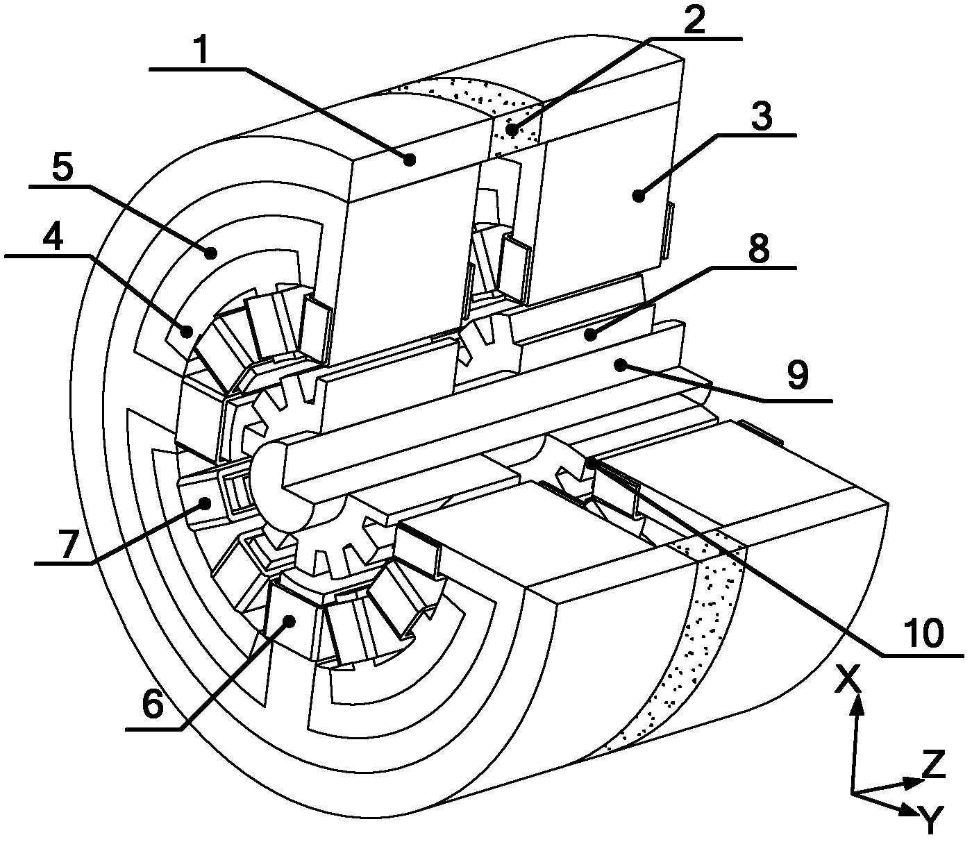
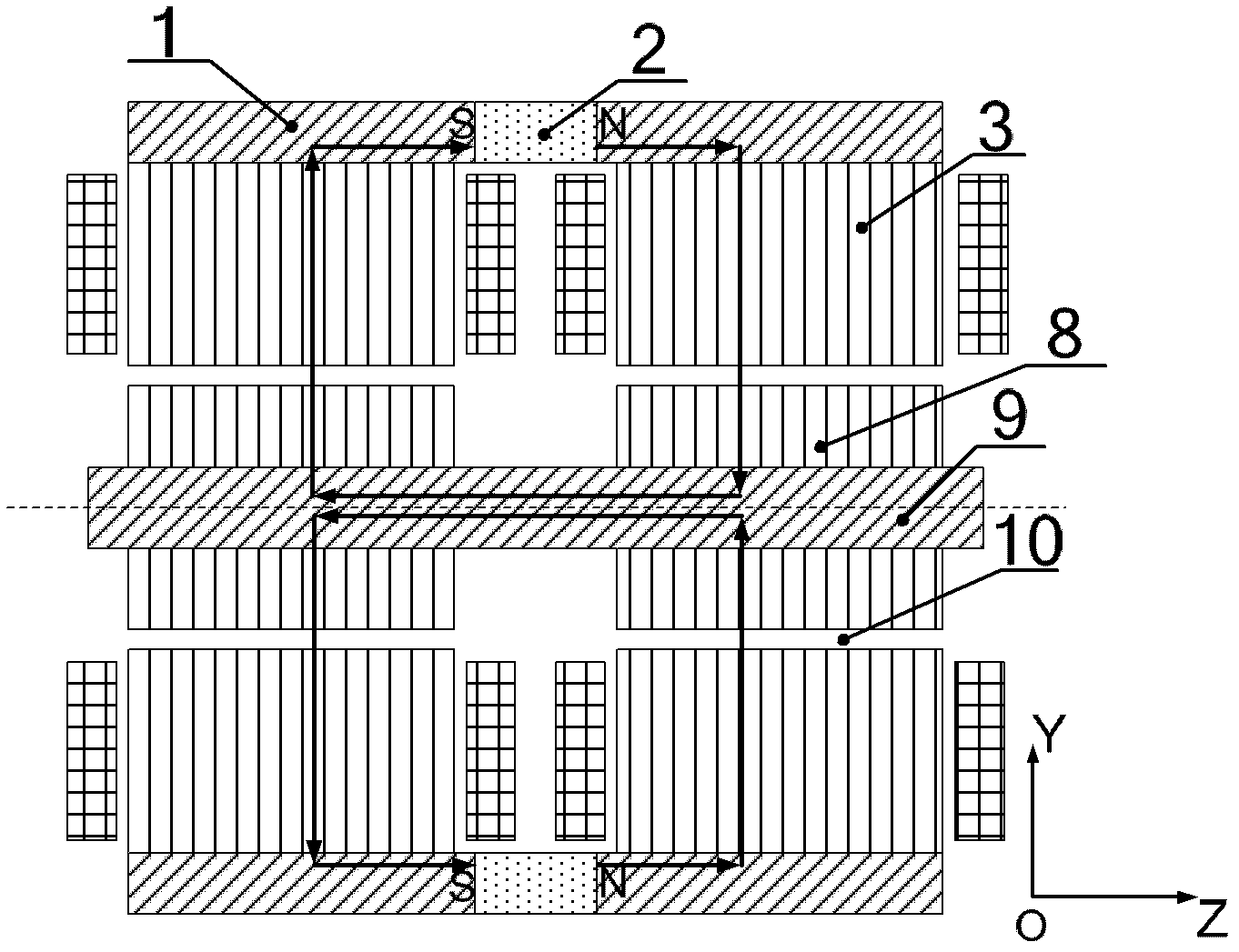
[0014] Such as figure 1 As shown, the permanent magnet bias bearingless switched reluctance motor of the present invention is composed of a stator back yoke 1, a permanent magnet 2, a stator levitation force core 3, a stator torque core 4, a magnetic isolation sleeve 5, a levitation force winding coil 6, Composed of torque winding coil 7, rotor core 8, and shaft 9, two stator suspension force cores 3 form permanent magnet bias bearingless switched reluctance motor with 8 magnetic poles at the left and right ends, and each stator suspension force core 3 forms a permanent magnet Offset bearingless switched reluctance motor has 4 stator poles (also called stator teeth) in the positive and negative directions of X and Y at one end, and each stator levitation core 3 has 4 teeth, and each tooth is wound with a levitation force Winding coil 6, the outer side of the stator suspension force core 3 is the stator back yoke 1, the stator back yoke 1 is connected with the stator suspensio...


PUM


Abstract

The invention discloses a permanent magnet biased bearingless switched reluctance motor, which comprises stator back yokes, permanent magnets, stator suspension cores, stator torque cores, magnetic shields, suspension winding coils, torque winding coils, rotor cores and a shaft, wherein the stator suspension cores are wound with the suspension winding coils; the stator back yokes are arranged outside the stator suspension cores and connected with the stator suspension cores; the permanent magnets are arranged between the two stator back yokes; the magnetic shields and the stator torque cores are arranged in stator suspension core slots; the magnetic shields are positioned between the suspension stator windings and the stator torque cores; the rotor cores are arranged in the stator suspension cores and the stator torque cores; gas are reserved between the rotor cores and each of the stator suspension cores and the stator torque cores to form air gaps; and the shaft is arranged in the rotor cores. By the permanent magnet biased bearingless switched reluctance motor, decoupling control over torque and suspending power is realized to bring convenience to high-speed running; and a suspension biased magnetic flux is provided by the permanent magnets to reduce suspension power consumption and improve the efficiency of the motor.

Description

technical field [0001] The invention relates to a bearingless switched reluctance motor, in particular to a permanent magnet bias bearingless switched reluctance motor, which can be used as a driving motor for a high-speed blower and a compressor. Background technique [0002] With the continuous and rapid development of my country's economy, the problem of excessive energy consumption has become increasingly prominent. Facing the goals and commitments of energy conservation and emission reduction put forward by the country to the world, the energy conservation and environmental protection industry has been listed as the first of the seven emerging industries. At present, the power consumption of blowers and compressors accounts for more than 10% of the total power generation in the country, and the high-speed blowers and compressors based on high-speed motors do not need the step-up box, the volume can be reduced by 60-70%, and energy saving can be achieved by more than 20%....

Claims


Application Information

Patent Timeline
Patent Type & Authority Applications(China)
IPC IPC(8): H02K29/03H02P6/10
Inventor 王惠军刘西全王云燕杜国华高鹏飞王静雅
Owner 南京埃克锐特机电科技有限公司
Why Eureka
Try Eureka